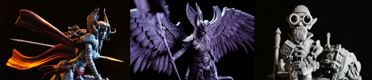
J3D-Tech’s Guide to Resin Printing, Beginners – Advanced
If you’re new to resin printing I strongly recommend
you first read the Terminology guide.
J3D Tech’s Terminology Guide to Resin Printing
Always wear Nitrile safety gloves, mask and safety glasses. Cure all resin waste, don’t just throw it away. Don’t dump/wash resin down a drain. Have proper ventilation.
YouTube Playlist of the Videos found in this guide.
For any additional help, find me Derek – J3DTech | Lychee Team and many others on the Lychee discord here.
This guide is based on Lychee Pro, you can Download the Free Version Here.
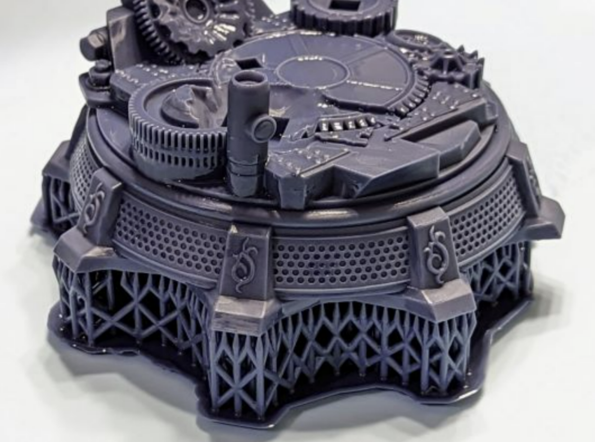
Failed Print (VAT CLEAN)
When you have a failed print or after a complex print and you’re not 100% sure of the success. Clean your resin VAT. The fastest and safest way to do this is to do a VAT clean. Removing the VAT to empty the resin is not recommended unless you suspect damaged FEP.
Video of me doing a vat clean with no resin, here. With resin and a bed level here.
Leveling The Bed
This is the most critical step you can take, it does not matter if everything is perfect. If your bed is not level, it will not print.
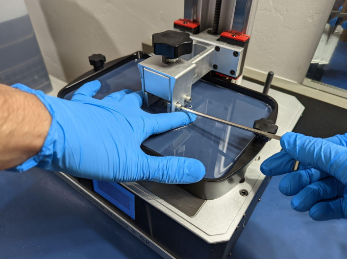
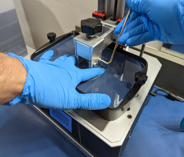
Vat method
This is my preferred method.
- Faster:
- No need to clean the build plate
- No need to remove the VAT
- No need to clean the LCD
- Cleaner:
- The paper method leaves resin oils, and paper fibers on the LCD. New paper & a very clean build plate only reduce this.
Even if your VAT has standoffs, the FEP can still touch the surface it’s placed on. Assuming you use LOTS of paper towels in the area. The tiny paper fibers will be attracted to the statistically positive FEP.
- The paper method leaves resin oils, and paper fibers on the LCD. New paper & a very clean build plate only reduce this.
- No layer compression typical with paper leveling. This will lead to better print quality and much better adhesion to the build plate.
- Messy:
- Your gloves get messy.
- Some Skill Required:
- The FEP is resistant to pressure. If you don’t keep pressure while you tighten you may need to level again.
- On Ball joint printers. It can be a little harder to make sure the plate is lined up with the LCD. However it does not need to be perfect as there are large tolerances on these printers.
Apply medium pressure on the plate. Lightly tighten in an X pattern. Don’t make them tight on the first pass. After about 4 passes. Reposition the wrench for the final tight, but not strip your bolts tight.
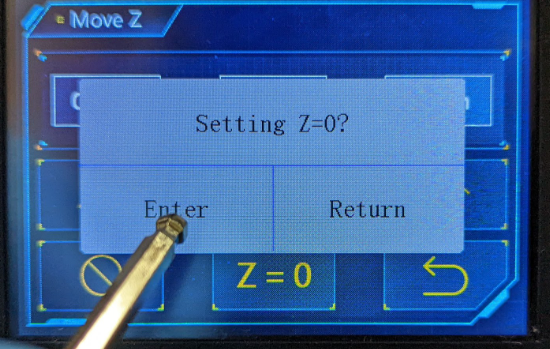
Reset Zero or Set=Zero.
Not all printers have this option. If yours does, it needs to be done right after you level, while the build plate is down against the LCD.
Paper Method
If you’re not sure how to do this, see your printers manual for the best instructions.
Printers with a ball joint like the Saturn series, my VAT Spacer is needed for VAT leveling.
If you’re more comfortable with paper leveling, or your printer is 13″ and larger:
- Use a sacrificial FEP sheet as your leveling method.
- This will better simulate your VAT.
- Won’t get paper fibers all over your LCD.
- Will protect your LCD from resin that may get though the paper from the build-plate.
- If you don’t have a spare FEP sheet, I recommend using 2 pieces of normal paper, or 1 if it’s very thick.
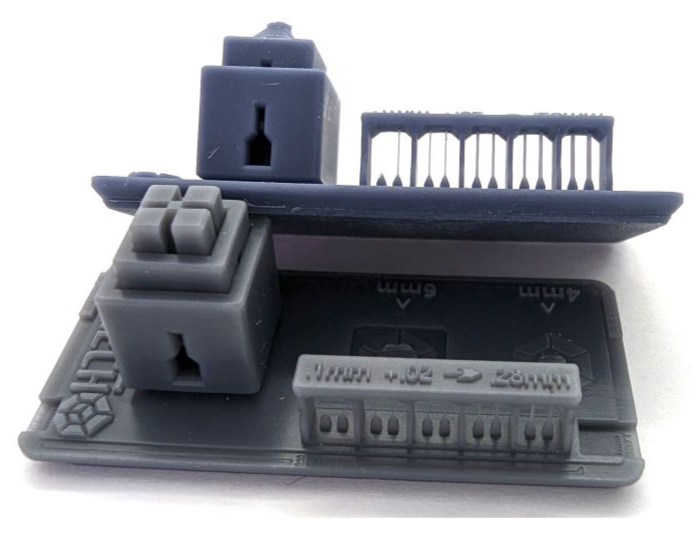
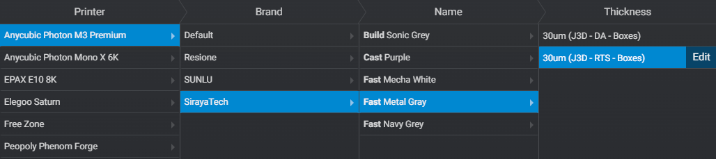
Calibration
In this guide I use Boxes of Calibration V2 found here.
A few things to remember before you in get started calibrating your printer.
- Most resins require 20c or even up to 30c. At the bottom of this guide I have some heater options. If you’re trying to print and calibrate below 20c, get a heater, it will improve everything.
- You will need to develop a calibration profile for each resin type, and layer thickness. For example, a clear or flexible resin will need very different settings then a hard opaque resin.
- There are two main methods of Calibration.
- Dimensionally Accurate – To successfully print exactly what you think you’re printing.
- Resin Tensile Strength – The maximum stress that a certain material can hold before it breaks.
- After calibration, failures are most often support or speed related issues.
Watch this video for instructions on how to use this tool.
Normal Layer Calibration Settings
Next you need to adjust your printer settings.
I’ll go over each setting, explain what it does and some direction of how to set it in preparation for the calibration print. Once you’re done with this section you will have a higher understanding then most users who have been printing for 1-2 years. You will also have developed your first perfect resin profile.
- Global Parameters Very Important!
- In Lychee, for some printers you will see (Global Parameters) If you don’t move on to #2. If available, pick TSMC. Having both on will trigger a Chitubox related bug that will cause neither to work correctly. The recommendation is to set TSMC to on, Light off Delay to off.
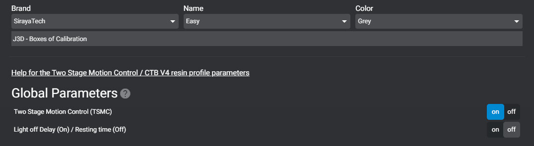
Turning on Two Stage Motion Control (TSMC) enables its use. However, using it will be discussed later in this guide; it’s not necessary for calibration.
- Light off Delay / Wait Before Print
- Gives time for the printer to come to full rest. Lesser known fact: When the motor stops the printer is still moving until the printer’s flex is fully at rest.
- Gives time for bubbles to escape
- I’ve seen no benefit above 2.0s. There is also a great article that goes into detail here.
- Your printer will have one or more of the following settings.
- Light off Delay (set to 1s)
- Wait After Retract (set to 1s) This is the same as Light-off Delay
- Wait Before Print (set to 1s) This is the same as Light-off Delay
- Wait After print (set to 0s)
- Wait After lift (set to 0s)
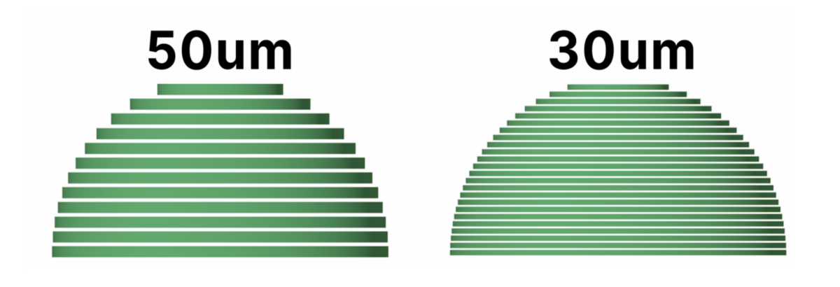
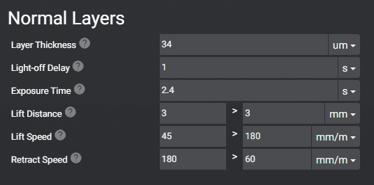
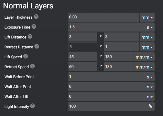
- Layer Thickness
- This is how thick each print layer will be. The lower the number the thinner the layer. Gaining more detail at the cost of longer print times.
- Objects with lots of curves or steep edges can benefit from more layers as it will reduce stepping. This is represented in the image below. The sharper the angle (the top) the more apparent stepping becomes.
- Once you have decided what layer thickness you want to calibrate your printer at, we can move to the next setting. (Default and most common is 50um)
- I print at 30um for show pieces, however larger objects like terrain and props for a D&D set I do recommend 50um or higher um. However you will need to develop a new profile.
- This is how thick each print layer will be. The lower the number the thinner the layer. Gaining more detail at the cost of longer print times.
Printed: 10um – NO AA – 100% Navy Gray & Mecha White – Anycubic M3 Premium*
*Many resins recommend not printing lower than 30um or 0.03mm. It’s possible to print at 20 or 10um, however you will want a slow retract speed (60mm/m) and light off delay of 4s or higher.
- Exposure time
- Use your resin’s recommended UV settings. This is the setting we are printing the calibration tool to adjust.
- How long will each layer be exposed to the UV light?
- Your slicer will have two settings for this. Burn-in / Bottom layers and Normal Layers.
- Use your resin’s recommended UV settings. This is the setting we are printing the calibration tool to adjust.
- Lift Distance
- Set this to 6mm. This setting will depend on the size of your printer and how stiff your FEP sheet is at any given time. The larger the printer, the more your FEP will flex. If you’re using a flexible resin you will also want to increase this setting.
- Pro Tip: To calibrate, watch a print during the burn in layers. You will see/hear it pop from the FEP. See how much further it travels. You want at most 2mm of travel after the pop. Some printers allow you to adjust this using the LCD while a print is going. Doing this will help you discover a default for all future prints using that resin. Flexible resins will require more distance.
- Pro Tip: To calibrate, watch a print during the burn in layers. You will see/hear it pop from the FEP. See how much further it travels. You want at most 2mm of travel after the pop. Some printers allow you to adjust this using the LCD while a print is going. Doing this will help you discover a default for all future prints using that resin. Flexible resins will require more distance.
- Set this to 6mm. This setting will depend on the size of your printer and how stiff your FEP sheet is at any given time. The larger the printer, the more your FEP will flex. If you’re using a flexible resin you will also want to increase this setting.
- Lift speed
- Set to this 40mm/m. This is how fast the build plate will rip the model off of the FEP after each layer.
- The faster the lift speed the higher chance of layer separation, support failure and build plate separation.
- The faster the lift speed, the faster your print will finish.
- Set to this 40mm/m. This is how fast the build plate will rip the model off of the FEP after each layer.
- Retract Speed
- Set this to 60mm/m. This is how fast the build plate will lower.
- With larger printers, it’s VERY important to slow down the retract speed. Lowering the plate with a large print will put a lot of pressure on the FEP and, more importantly, the screen. Some plates (like the Mega 8K one) have holes. The purpose is to limit the pressure to avoiding killing your expensive 8K screen.
- With larger printers, it’s VERY important to slow down the retract speed. Lowering the plate with a large print will put a lot of pressure on the FEP and, more importantly, the screen. Some plates (like the Mega 8K one) have holes. The purpose is to limit the pressure to avoiding killing your expensive 8K screen.
- Set this to 60mm/m. This is how fast the build plate will lower.
- Anti-aliasing
- Leave this off for all calibration tests. Will be discussed further in the guide.
Once finished it should look something like this:
- The Layer Thickness is up to you.
- Exposure time is based on your resin’s default recommendation. Probably between 1.5 and 2.5
None Chitubox Motherboards (Anycubic)
Chitubox Printer
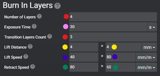
Burn-in-Layers / Bottom Layers Calibration Settings
These are the first layers printed and need to be exposed to UV light for much longer than normal layers. This is so the resin will adhere to the build plate during the remainder of the print.
None Chitubox Motherboards (Anycubic)
Chitubox Motherboard Printers
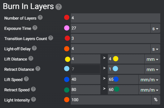
These settings ONLY affect the first layers printed in this example, only the first 4 layers.
- For Exposure time, use your resin manufacturer recommended settings. This can always be calibrated later.
- For burning in Layers, this will directly impact how well the print sticks to the build plate.
- Every resin is different, calibrate this for resins and printers.
- Go up or down by 4s till it comes off easily but still holds firm
- Go up or down by 4s till it comes off easily but still holds firm
- Go up or down by 4s till it comes off easily but still holds firm
- Develop a different burn in time for each size of print.
- Small = calibration print or small parts
- Medium = Minis or parts of a larger print
- Large = Terrain or a very large statue
- Using Navy Gray a “Fast Resin” I’ve found my number are around:
- 15-24s for small
- 27-34s for medium
- 35-40s for large
- Transition Layers will transition away from the burn in layer settings to the normal layer settings.
- After you disable Light-off Delay in Global Parameters, your printer most likely will not have a dedicated setting under Burn In Layers. If it does, set it to 4s, otherwise leave it at 2s.
- Lift Distance Set this to 25% higher for Burn in Layers over Normal Layers. This is because these layers will be the most difficult for your printer to remove from the FEP. The result of larger cross sections and longer burn in time.
- Lift Speed should be slow for burn in layers. No greater than 40mm/m. This is because as stated before, these layers are very difficult to remove from the FEP.
- Retract Speed needs to be set very slow for Burn in Layers. This is because the build plate is trying to push the resin against the LCD under incredible pressure. So much pressure that the frame and arm of your printer will flex and bend.
- If your model is hard to remove from the build plate remove 4s from Exposure Time till they are firm but easy to remove.
- If your models keep falling off the build plate and your exposure is already above the resin manufacturer recommended. Try the following Instead of burning out your LCD light by adding more Exposure time.
- increasing surface area on the build plate by using a larger raft.
- Slowing down your retract speed to 40mm/m or lower.
- If your printer does not have a separate retract speed for burn in layers. Try lowering it down to about 60mm/m.
.
Slice and Export Test Files
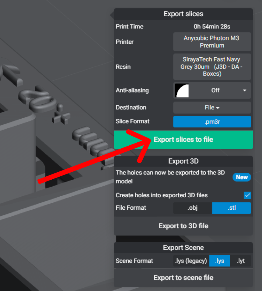
To save time, slice and save multiple files at once. Do this by increasing Exposure Time by + 0.1s.
Export to your Computer’s SSD
Do not export directly to a USB as this has a high risk of causing data corruption and failed prints.
Copy to a USB
Use a high quality USB. The provided USB can cause data corruption and failed prints.
Do this for all your printers and print. Not just calibration prints.
For more advanced users install and run UVTools to check the slice before you copy it to the USB drive to confirm it’s free of slicing errors. (Video TBA)
Prepare your 3D printer
Prepare your printer for the next print by using the Clean or Squeegee methods. Do this after or before every print, always! Failure to do this will lead to permanent damage to your 3D printer.
Continue reading for how to Squeegee your FEP as the preferred method. If you don’t have a silicone spatula see “Cleaning your FEP” for instructions.
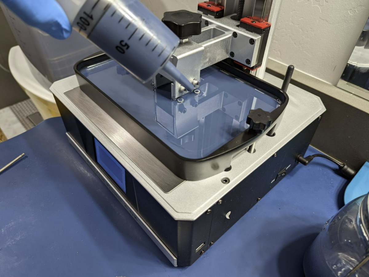
Mix your resin & Squeegee your FEP
Before every single print mix the resin. Use a soft silicone spatula to squeegee the FEP before adding new resin. This is also to check for any solid objects stuck to the FEP. When adding resin, shake the bottle for at least 30s, pour and let sit for 5-10 min allowing the bubbles to dissipate. Amazon Link for the spatula shown.
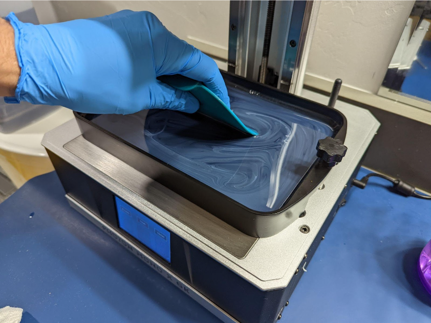
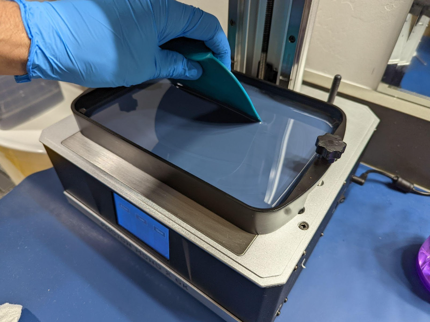

Don’t use the hard plastic scraper that comes with your printer, it will scratch the FEP. If your FEP is damaged, I do recommend getting an nFEP.
Now you’re ready to print your first calibration!
So go do that now. While you’re waiting, grab a coffee and read the rest of the guide.
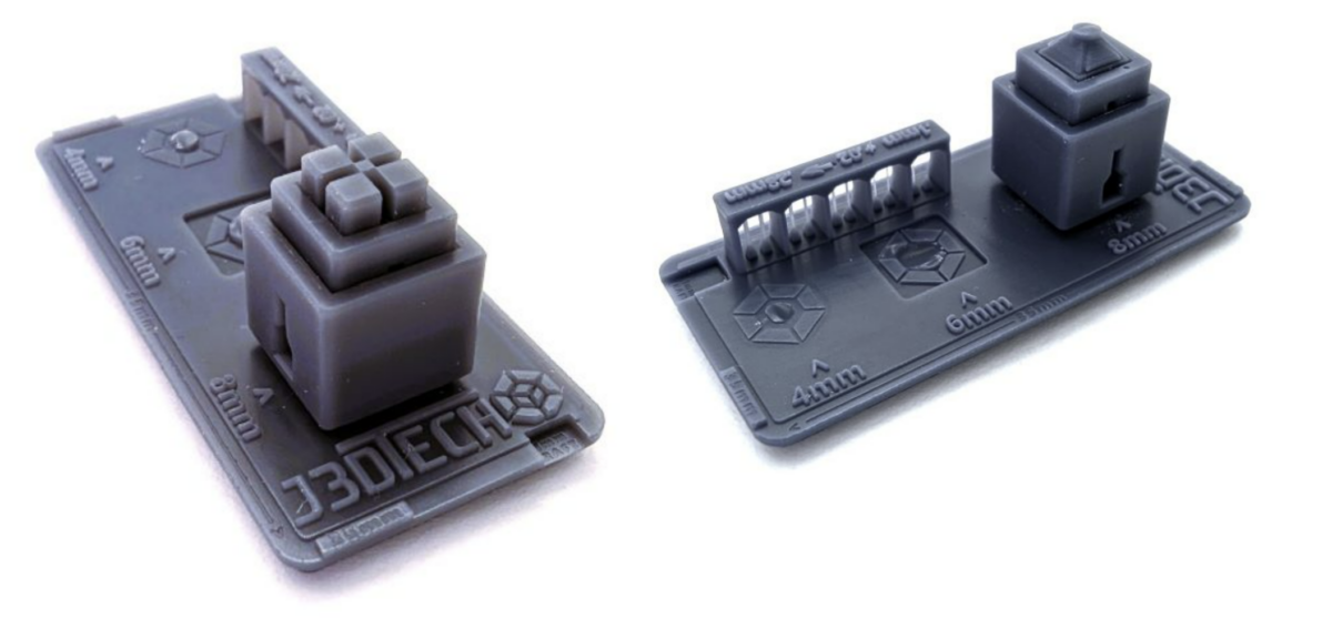
Reading Boxes of Calibration
Download Boxes of Calibration V2 here
Added function! If you’re not new to my guide, please review this section again as there have been some exciting discoveries! See “Function 2”
Now that you have printed your first test print, let’s go over how to read it to tune your resin to your printer. This is where the magic happens.
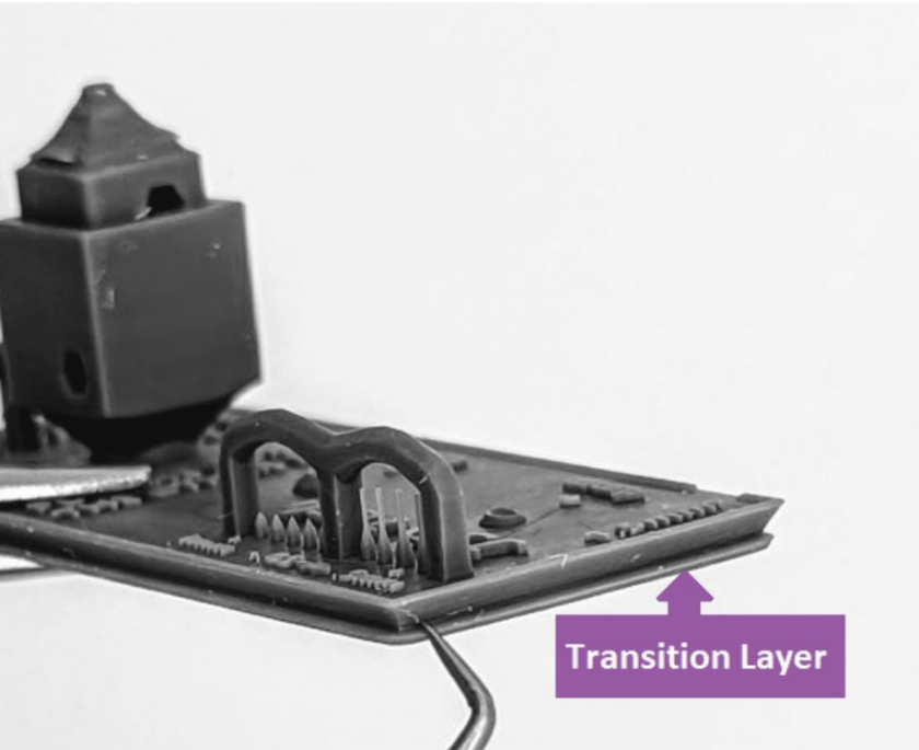
Transition Layer – Elephant’s foot
If the number of Burn In layers is set to high or over exposed (High Exposure Time) they can bleed into your supports and cause supports to break off at the raft for all future prints.
You can visually see if this is the case on your first test print. Look for the transition layer between the burn in and normal layers. You want this Transition Layer to take place within the Base/Raft like the picture below.
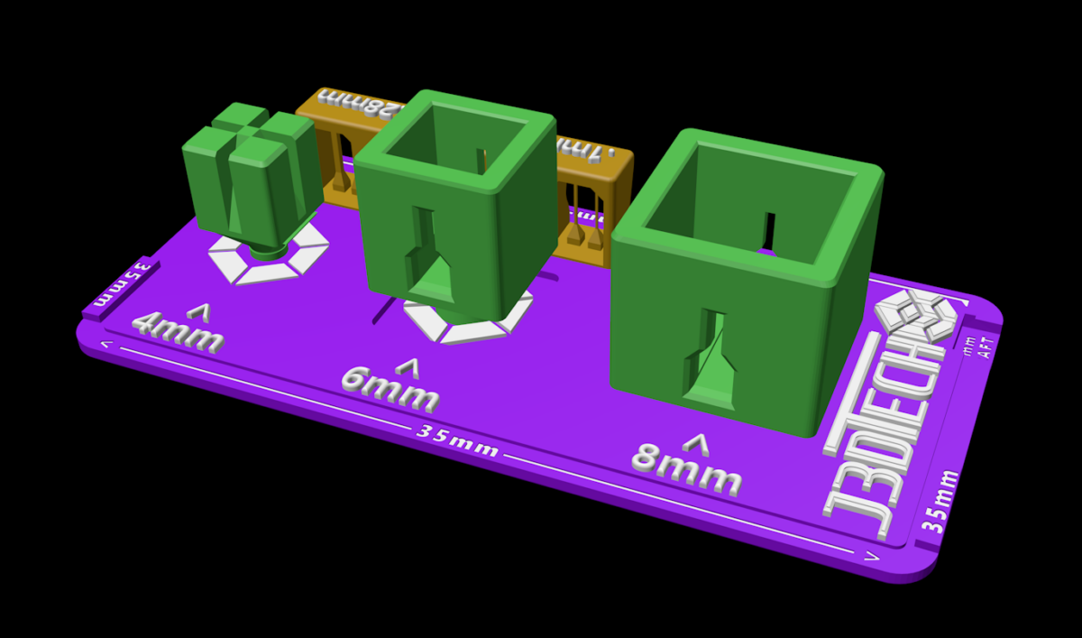
Boxes of Calibration
If you don’t have digital calipers
That’s ok, all you need to do is snap off the 4mm and 6mm Boxes. Once they fit inside of each other where you can still pull them apart you’re good to go.
- Are they too tight: Reduce the Normal Layer UV Exposure time.
- Are they too loose? Add Normal Layer UV exposure time.
- Reduce or Add time by 0.3 s until you’re close, then 0.1s to get them perfect.
- To prevent damage to your FEP: Rotate them 90d and move them by a few mm’s each print. This is true for any file you print more than one time.
If you have a pair of Digital calipers
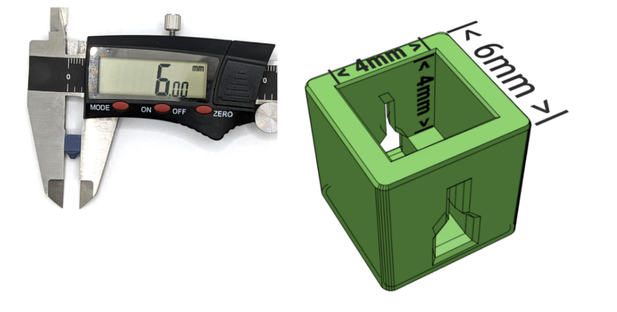
Snap off the 4mm and 6mm Boxes, to allow measuring all the boxes easier.
To measure the The inside of each box:
6mm box’s inside should measure 4mm x 4mm x 4mm.
8mm box’s inside should measure 6mm x 6mm x 6mm.
Pillars of Resin Tensile Strength
Do not not overlook this feature, it can be very powerful as it makes this calibration file two in one, the first of its kind!
Function 1:
Feedback at Dimensional Accuracy
Once you have reached dimensional accuracy you can now pay attention to the pillars.
- They will tell you the tensile strength of your resin at dimensional accuracy calibration.
- The more pillars the higher the tensile strength.
- This data is very necessary as it will help you understand what sizes will likely fail when doing your own supports, or printing pre-supported items.
- Some high quality resins will print all pillars and retain Dimensional Accuracy. If this is the case you have already achieved Function 2.
Function 2:
Increased Success for Pre-Supported Models.
Calibrate your resin to TRUE Resin Tensile Strength!
- Simply keep increasing Normal UV exposure till all the pillars print.
- This will greatly increase the success rate of pre-supported models.
- The boxes will most likely no longer fit. However they will provide feedback of how much accuracy you’re trading for higher success rates.
- Save this calibration as a New Resin Profile, I suggest:
- “DA – Boxes” DA for Dimensional Accuracy
- “RTS – Boxes” RTS for Resin Tensile Strength
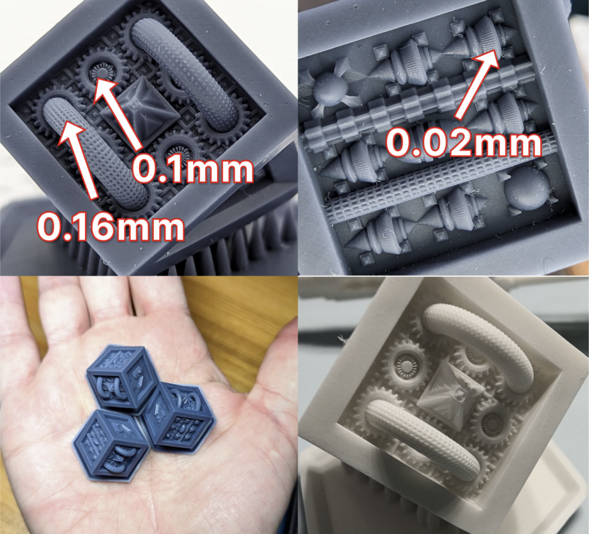
In this example for the 85%Navy Gray + 15% Siraya Tenacious Obsidian Black we can use maybe 0.12mm but it would be safer to use the 2 steps up one up .18mm as our smallest support tip.
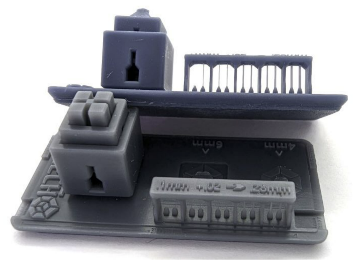
The smallest Pillar is 0.1mm. Each pillar is 0.02mm thicker than the previous going left to right.
Baseline!!
Once your Boxes are dimensionally accurate you have a Baseline, we will reference this for all future prints. Save the resin profile in your slicer as Boxes of Calibration.
Example of saved profiles in Lychee
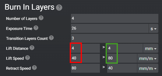
Two Stage Motion Control, (TSMC)
Not all printers support this, if yours does, these numbers are ONLY EXAMPLES! Please develop your own as my examples may not work for you.
Primary Objective: Speed up your print time while keeping the same accuracy and success rate.
Objective 2. Have the model Pop from the FEP 98% of the time during the slower Lift Speed.
Objective 3. Have enough safety margin in the faster Lift Speed to NEVER have a failed FEP release.
Objective 4. Not having excessive heights as to add unnecessary print time or, worse, lifting the print edge of the model out of the resin as this can cause air to get mixed into the resin.
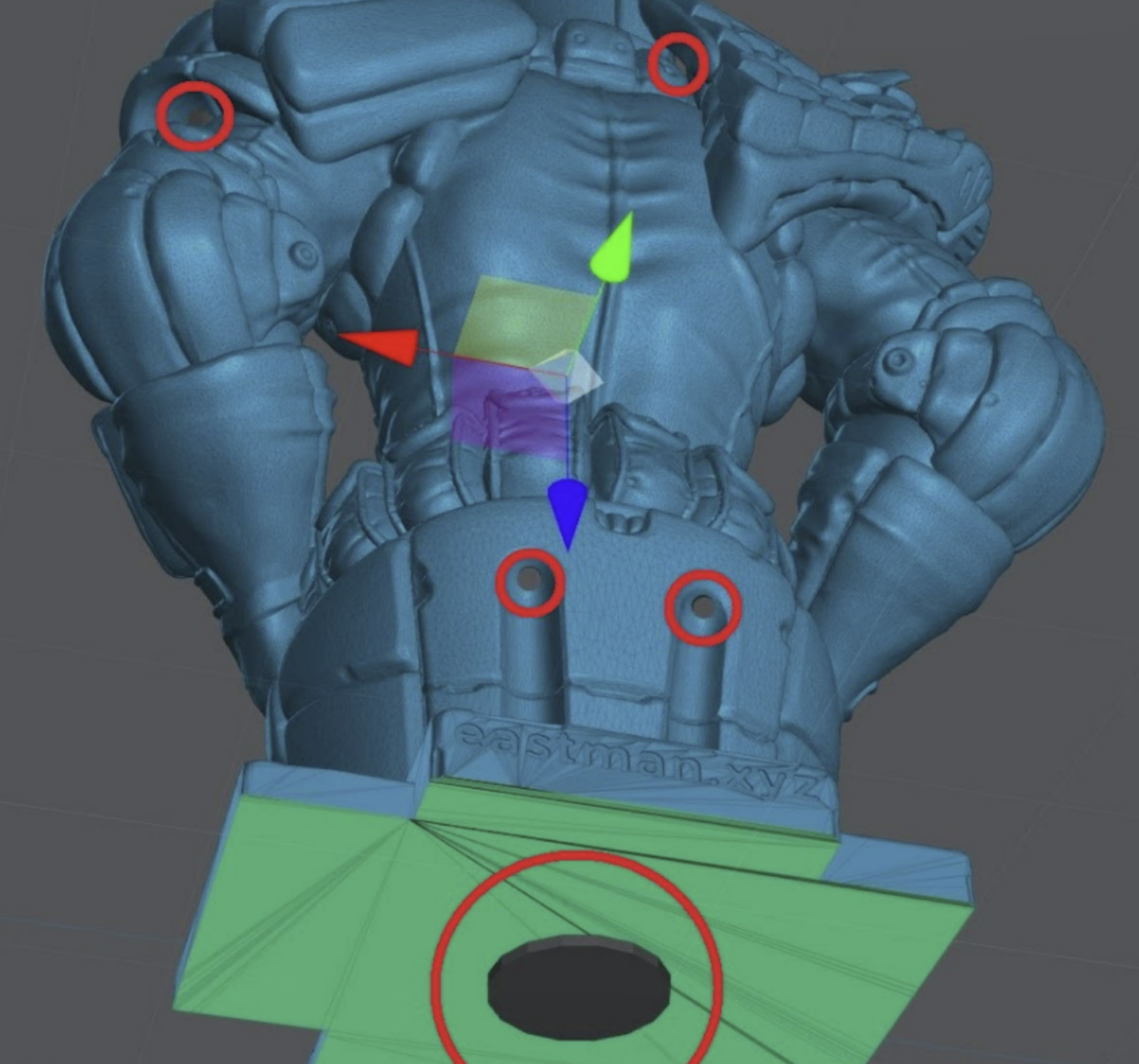
Now that you know what Lift/Retract distance and lift speed are, let’s apply that knowledge. The colored circles show you what settings are linked together.
Burn-in / Bottom layers
In this example, I’m lifting the plate a total of 4mm. 40mm/m for the first 2mm PLUS 80mm/m for the final 2mm. That’s right, as I stated before these numbers are added together.
For Retract speed you will notice that the lower number is in the right field.
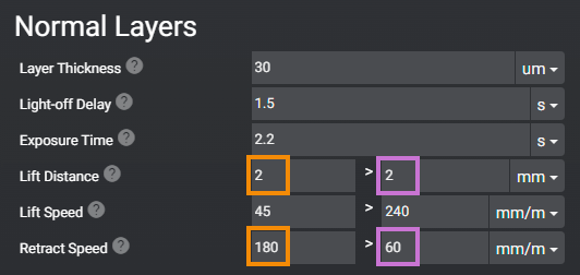
Normal Layers
In this example, I’m lifting the plate a total of 4mm. 45mm/m for the first 2mm and 240mm/m for the final 2mm.
For Retract speed you will notice that the lower number 60mm/m is in the right field.
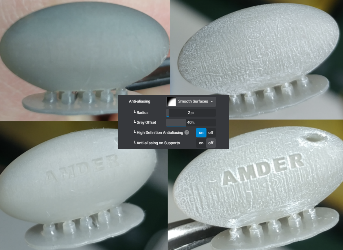
Anti-aliasing
(Remember Not used for calibration)
I won’t spend much time on this as others like SnarkyArts did the hard work and tested almost every combination.
What is shown below is the best setting for AA. Many other AA settings offered little to no difference, however this setting is magic.
I did confirm the findings before adding it to this guide. Find us on the Lychee Discord and join the adventure.
| Lychee Version 5.0 + | Chitubox |
|---|---|
| Anti-aliasing – Smooth Surfaces Radius 2px Grey Offset 40% High Definition Anti Aliasing On Anti-aliasing on Supports Off | Anti-aliasing Level 2 Gray Level 1 Image Blur 2 |
In my tests I was able to remove layer lines and voxels from this axe without affecting details.
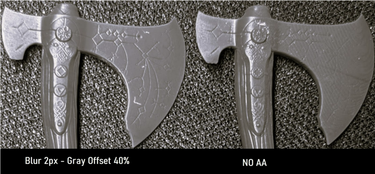
This example proved by SnarkyArts you can see that the lines are not completely gone, but only show under the harshest conditions.
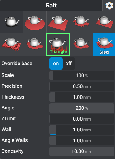
Rafts
Minimum .7 mm thickness, best to use 1mm to absorb the burn in and transition layers.
There are many types of rafts to choose from. What one you choose is up to you as long as you pick one. However I do recommend the “Sled” or “Line Triangle in Lychee”.
I’ll use the Triangle raft for large bases or anything with a massive surface area on the build plate.
The Sled raft is best for much everything else. The lip makes it easy for the scraper to get under and pop the print off of the build plate.
Model Sizes
Now that your bed is level and you have your baseline it’s time to apply it to the different sizes of models.
Small Models
Small prints are very forgiving. You can also get away with a lower burn in layer time. Often around 15 seconds.
Example of small Models
Medium Models
Medium model settings will be used the most. They can be used for small to medium large prints. Add 4 seconds to your Burn In layers exposure time.
Calibrate burn in time for the size of the model. See this video.
Example of Medium Models
Large Models
Larger objects come with new issues: gravity and large cross sections increasing suction force.
Suction force is the pulling force your printer has to use to pull the model off of the FEP.
- Add ~10 seconds to your burn in layers and slow down your lift speed to 40 mm/m.
- For thick models with a large cross section you have to have light off delay of 1-2 seconds for normal layers.
- If your printer allows independent “burn in” layer “light off delay”, do 5 seconds.
- Always hollow large models if you can, more on hollowing to follow.
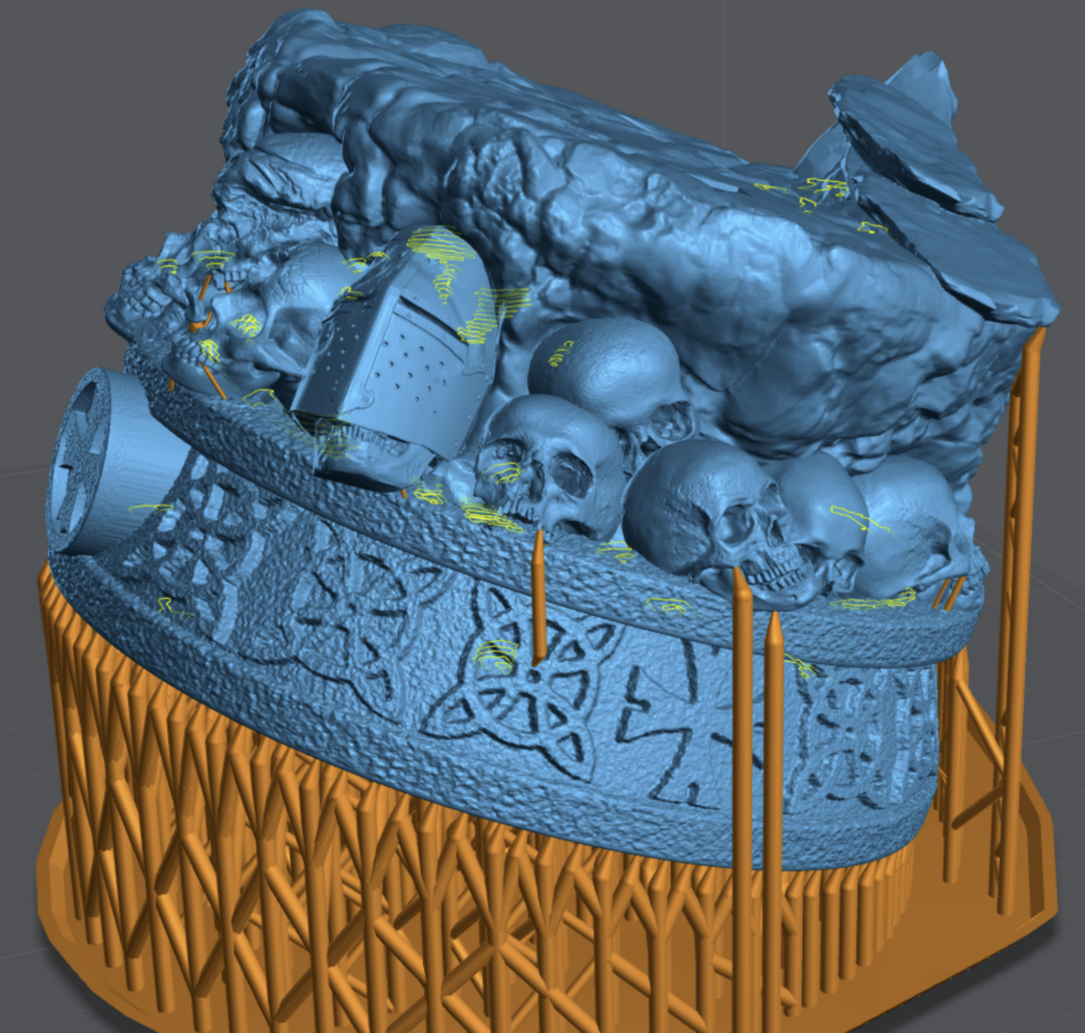
Example of Large Model on a 10.3″ Build plate
The horrid truth about 90% of pre-supported models.
If you followed this guide to this point, you’re in a minority. A minority that took the time to calibrate your printer and obtain some knowledge.
Unfortunately some pre-supported models are supported for those that print, for example, 4 seconds per layer, when under 2 seconds is optimal.
This truth and other factors such as “It’s pro to use less supports.” or “It’s pro to use tiny support tips.” has made the industry trend to undersupport models.
Because of this, I highly recommend you read the rest of the manual and support your own. Or at minimum apply what you learn and add supports to pre-supported models before you press that “Print” button.
Model Orientation
Skyscraper Orientation Method
Pros
- Amazing precision and detail.
- Less supports overall.
- Reduced Layer lines on hard surface modeling
Cons
- Longer print times.
- Lots of supports on the surfaces towards the build plate.
- Can sometimes not be possible unless you know how to alter a 3D file.
Objective #1. Orientate the model so that it supports itself. The object is your best support; use it.
Objective #2. Orientate so the surface you care about the most is facing the top or sides of the print. Never put visible details you want to preserve facing the plate.
Objective #3. When dealing with a large flat surface, like a base. Add tilt to help build that flat surface over several passes. As long as it does not overly interfere with objective 1 and 2.
Traditional Orientation Method
Pros
- Shorter print times
- Can focus on reduced cross sections over all other objectives.
Cons
- 45 degree rue is subjective and often incorrect
- Supports end up on visible surfaces
- Lots of supports all over the model
- Tall supports that often are almost the height of the print requiring a lot of bracing.
Traditional supporting vs Skyscraper Methods.
On the example below, supports will be on the exterior and final details of the model. As you can see there are supports on; back of the foot, blades and hand shield. The kilt and mask will have support damage facing up towards the viewer when assembled.
Example of Traditional Orientation Method
On the example below, the models are facing up like a skyscraper to build on top of itself. Supports are under folds, or surfaces that will point down or inside joints that will be glued. Overall there are more supports to be sure the model will print, and hold it’s shape.
Example of Skyscraper Orientation method – More examples found in the “Supporting” chapter

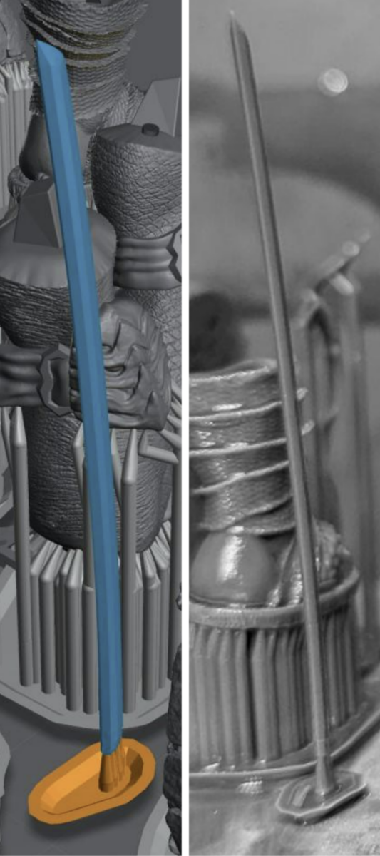
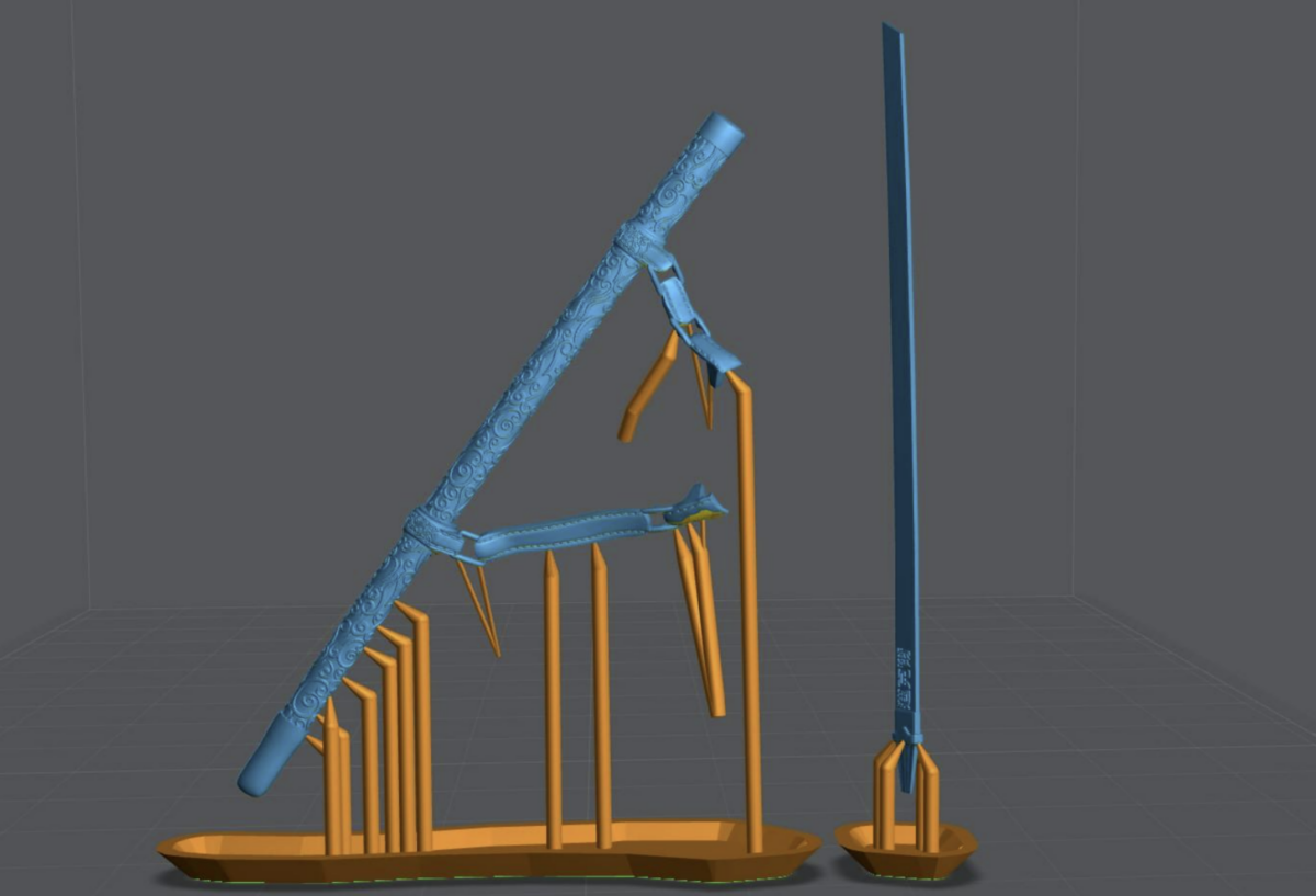
Tolerances in the microns
For some objects the only way to get accuracy you need is to print them straight up, Like a skyscraper. Below are some examples of objects with 0.01mm or 10 microns tolerances.
This moving track has over 90 links and was printed as a single part. Only possible using this Method and a very good resin. For this print used 100% Siraya-Tech Navy Gray.
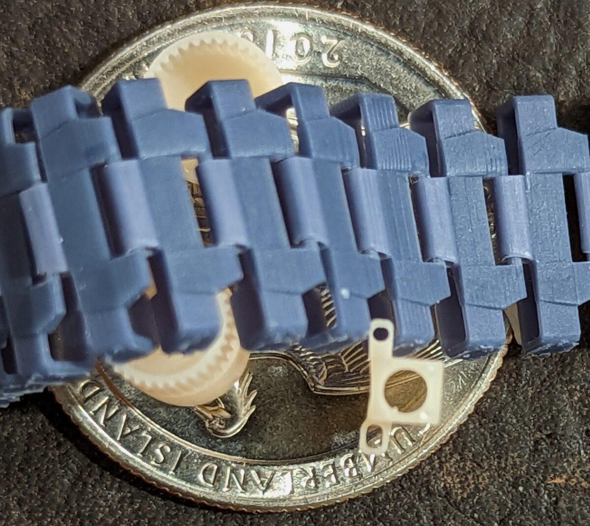
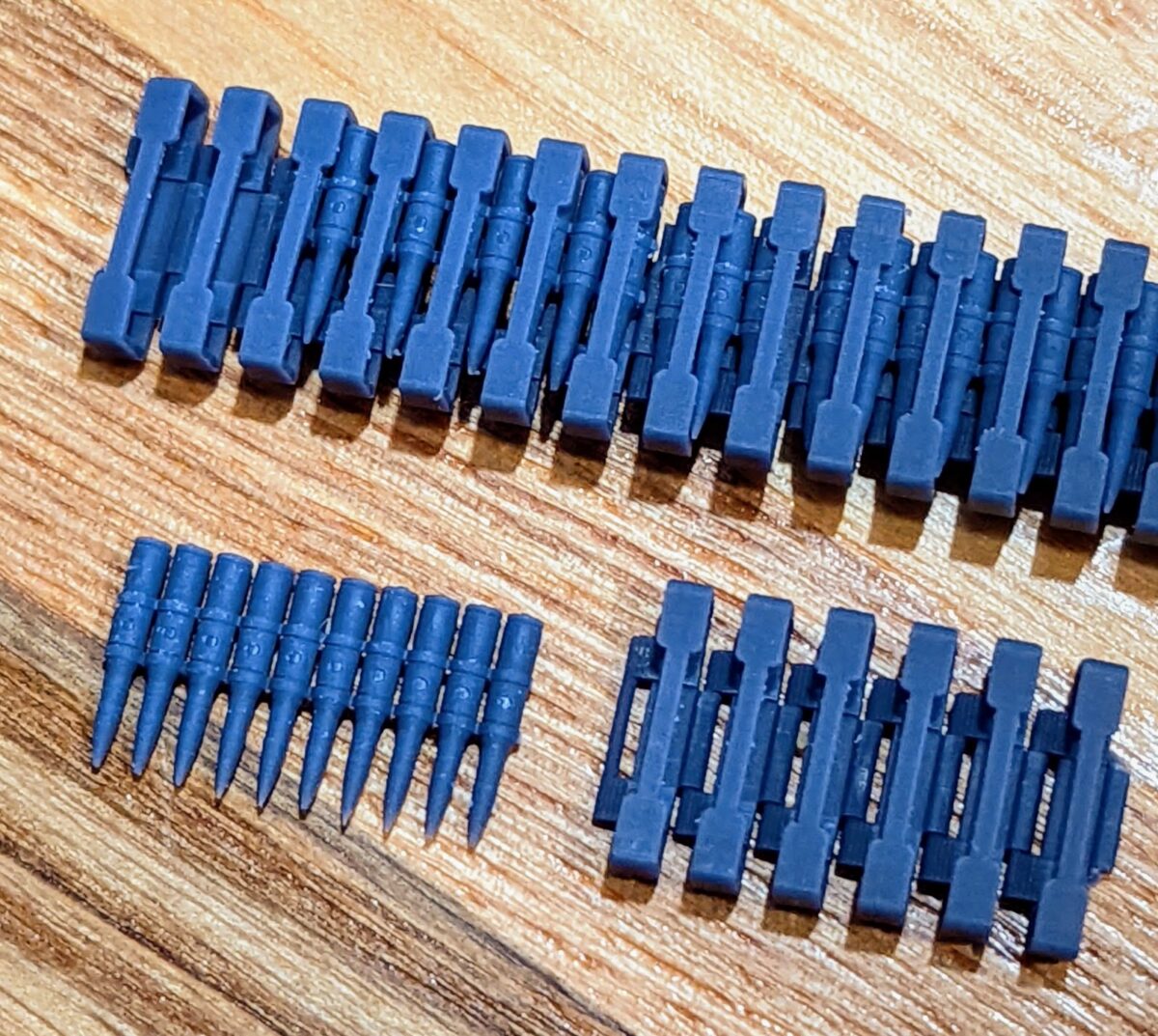
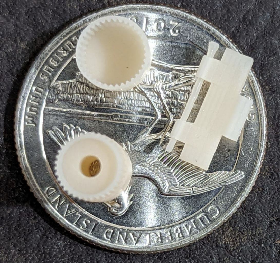
To visualize the track above I printed it as multiple parts. The size of the pin hole is 0.376mm and the pin is 0.354 mm. That’s .022mm total but I need a gap around the entire pin, that’s 0.011 tolerance! I also printed gear with a cap that has 0.008mm of tolerance
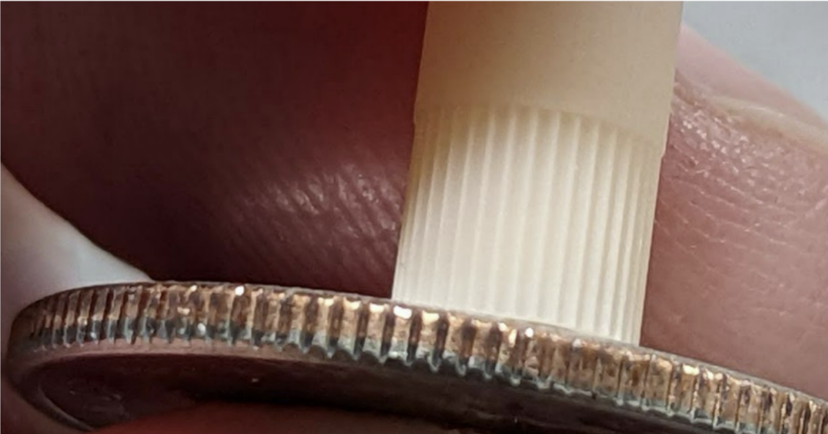
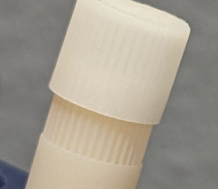
Notice the ridges compared to the ridges on a US Quarter.
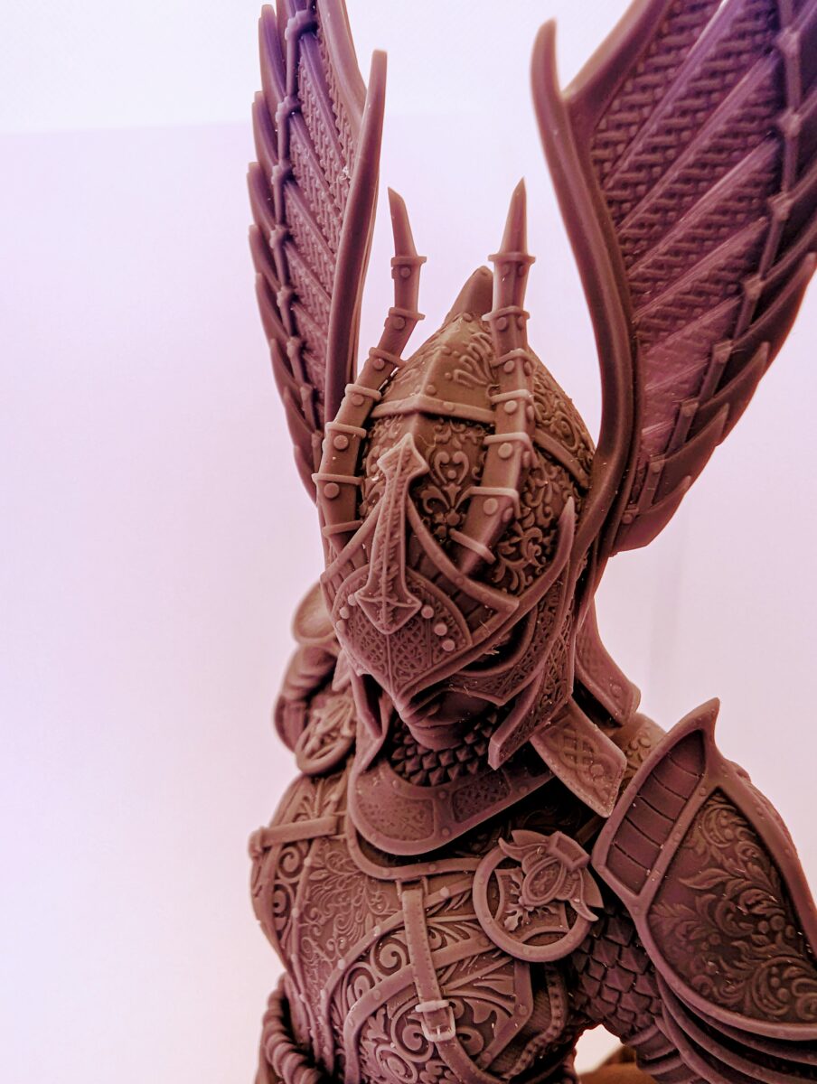
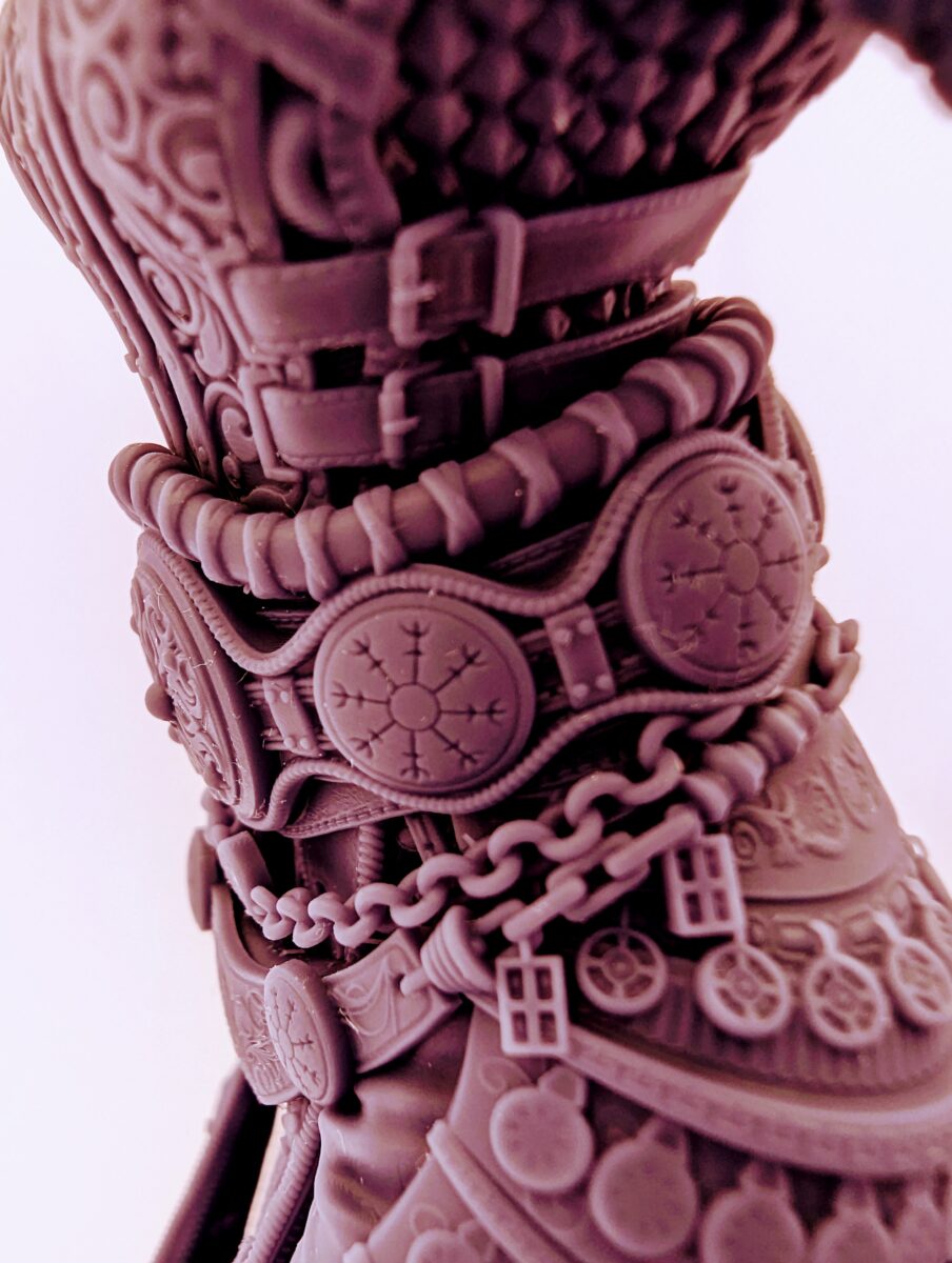
For miniatures this means more detail. This also works for tall thin objects like Leonardo’s sword. Mulan’s sword (shown below) is so thin you can see through it. Until it was cured it would fold over. Yet the final product still has amazing detail and holds its shape even after a year+ on the shelf
Supporting
There are four types of supports; structural, shape, detail, and bracing.
- Structural – Supports to hold the model to the build plate.
- These are often the largest tips and found at the bottom of any major island.
- These are often the largest tips and found at the bottom of any major island.
- Shape – These are the supports that maintain the shape of your object.
- You may find that your model will print with very few structural supports but your print will be warped. Adding “Shape” supports between structural supports will resolve this issue.
- You may find that your model will print with very few structural supports but your print will be warped. Adding “Shape” supports between structural supports will resolve this issue.
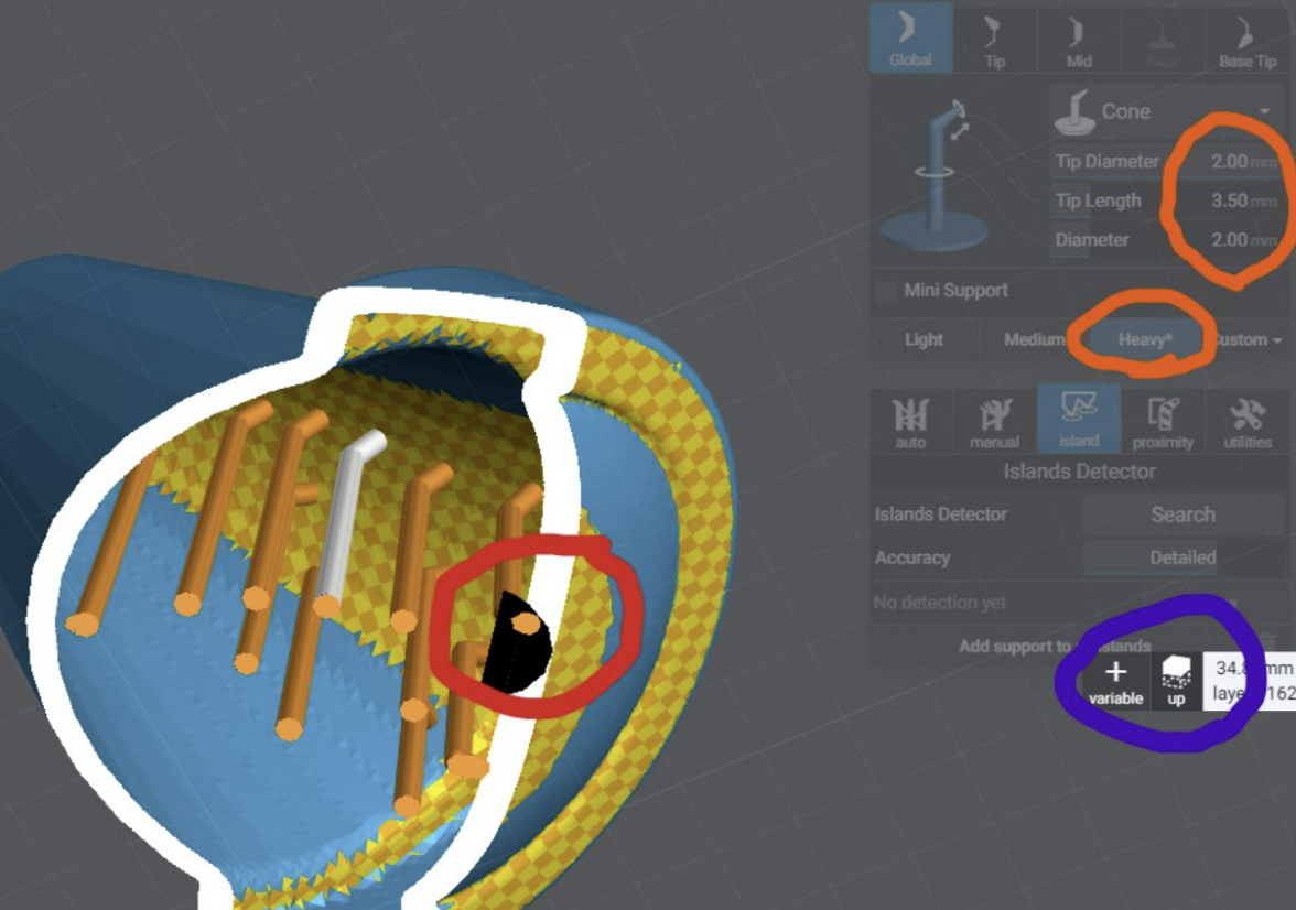
- Detail – These are your smallest tip sizes, used to support small islands that lead to fine details of a model.
- Don’t place a support on every island. If the island is under 4 or less layers or smaller than your support tip, you will often cause more damage adding a support then leaving it alone.
- Don’t place a support on every island. If the island is under 4 or less layers or smaller than your support tip, you will often cause more damage adding a support then leaving it alone.
- Bracing – Used to keep anything from shifting side to side during the print.
- Just as bracings are used between support shafts to keep them from shifting. Bracing supports also need to be used to keep your entire model from shifting during the print.
Author’s Note: It’s important to understand, once you have your printer dialed in for Burn-in and Normal layer exposure. Over 95% of print failures are a result of bad supports, NOT bad printer settings.
When supporting, follow the same logic mentioned previously regarding model sizes. Small, Medium, and Large Models.
These support profiles were developed to get the best shape, detail and print success using my Boxes Calibration tool
| Light: Tip Diameter 0.3mm Tip Length 2.5mm Diameter 1.0mm | Medium: Tip Diameter 0.4mm Tip Length 2.5mm Diameter 1.3mm | Heavy: Tip Diameter 0.7mm Tip Length 3.0 Diameter 1.8mm |
| Ultralight Tip Diameter 0.24mm Tip Length 2.5mm Diameter 1.0mm | Medium-light: Tip Diameter .35mm Tip Length 2.5mm Diameter 1.20mm | Interior Pillar Tip Diameter 1.5mm Tip Length 2.0mm Diameter 1.50mm |
If you have Lychee Pro you can DL and import my support settings here
Supporting Bases
Helpful Tips: Mastering Lychee Supports: Watch my video here
Watch my video on how I supported this base here
Supporting Small Models
With Small models you can get away with:
- Entire works of art in a single print
- No heavy supports used at all.
- Almost no light supports needed to retain small details.
- No hollowing
Just because you’re printing a small model does not mean you can now use light supports. Medium supports are for keeping shape and holding your print to the build plate. Light supports are ONLY for keeping detail.
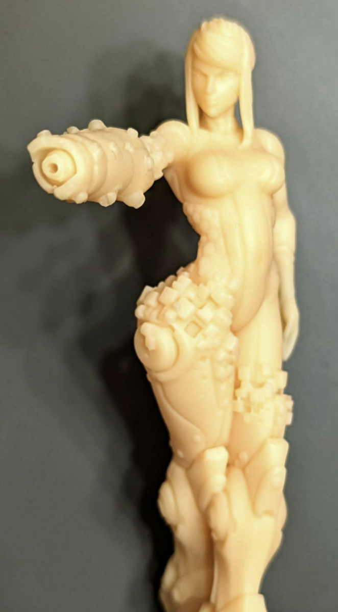
Mulan Sword Example, Modeled by https://www.patreon.com/sephon/posts
The blade is not curved at the end, it just looks that way because of how the light passes through it.
In this very small sword and sheath we have some extremely tiny details and a sword that’s under 1mm thick. Using these settings such prints are very possible.
Only light supports are visible, only to preserve details.
Only medium supports are visible, used to anchor the models.
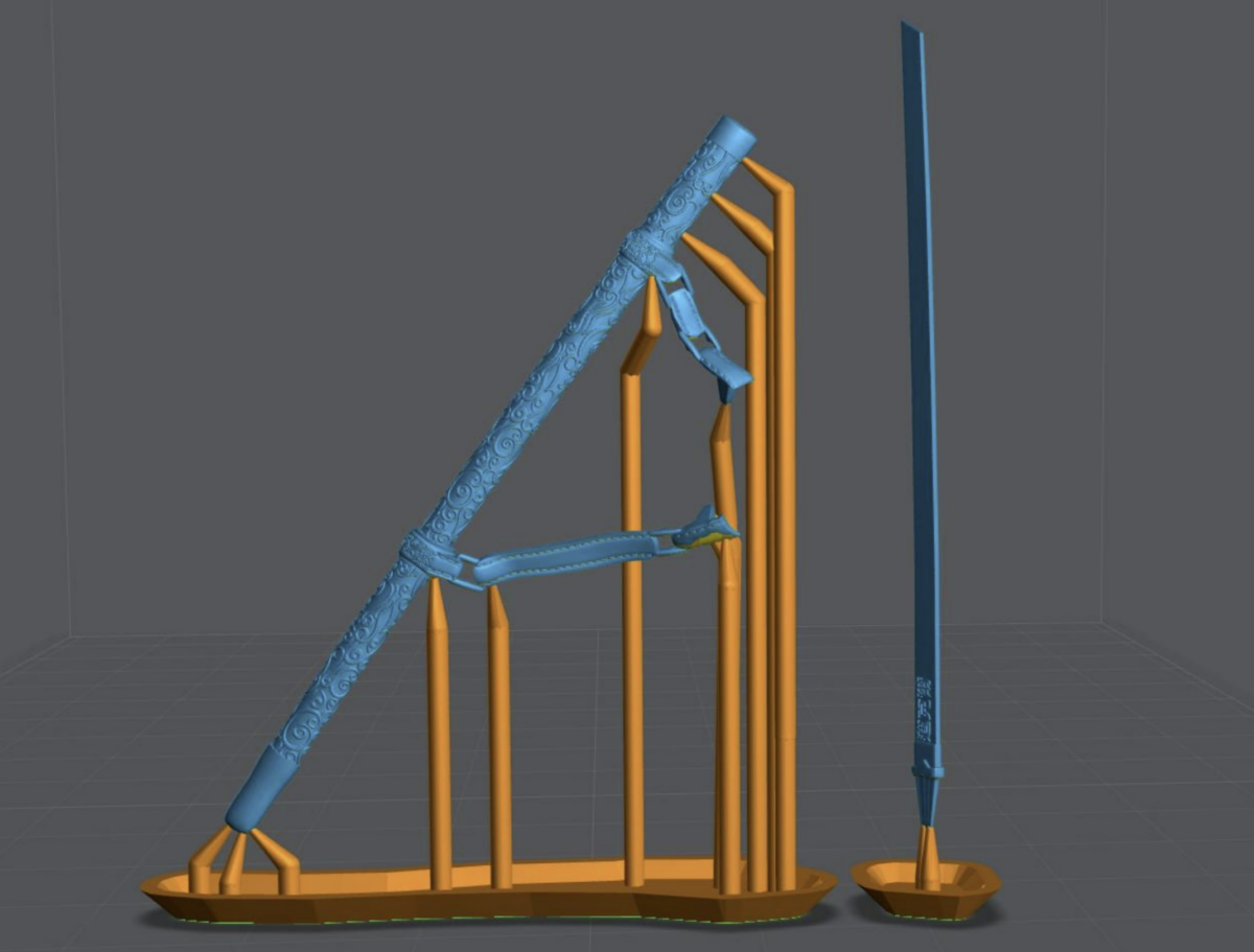
All Supports visible. Scroll back up to get another look at the finished print.
Supporting Medium Models
With Medium models you can get away with:
- Entire works of art in a single print
- One heavy support per model or major outcrop.
- No hollowing on thinner objects
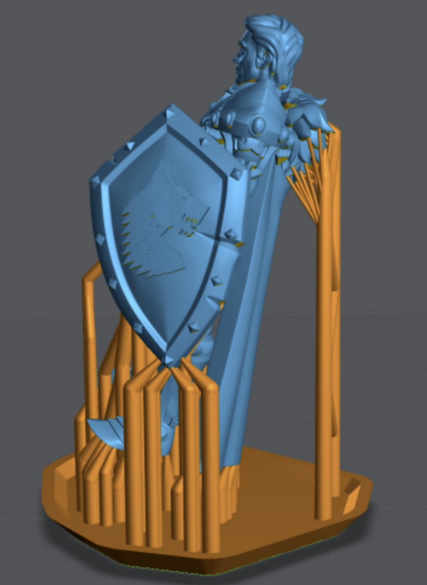
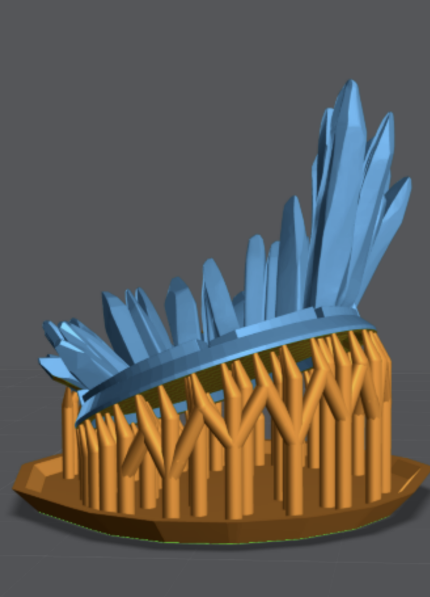
Warrior Example
In this example of two medium models. You can see the use of the Skyscraper method in play. Pay close attention to the average direction of the crystals, shield and cloak.
Also notices how MANY medium supports are used to preserve the shape of the base. Think of a reverse bed of nails. The more nails the less pressure. There are no heavy supports used. Mini supports used to keep the details of the cloak.
Also pay close attention to the tip of the shield. Always support downward facing tips on multiple sides.
.
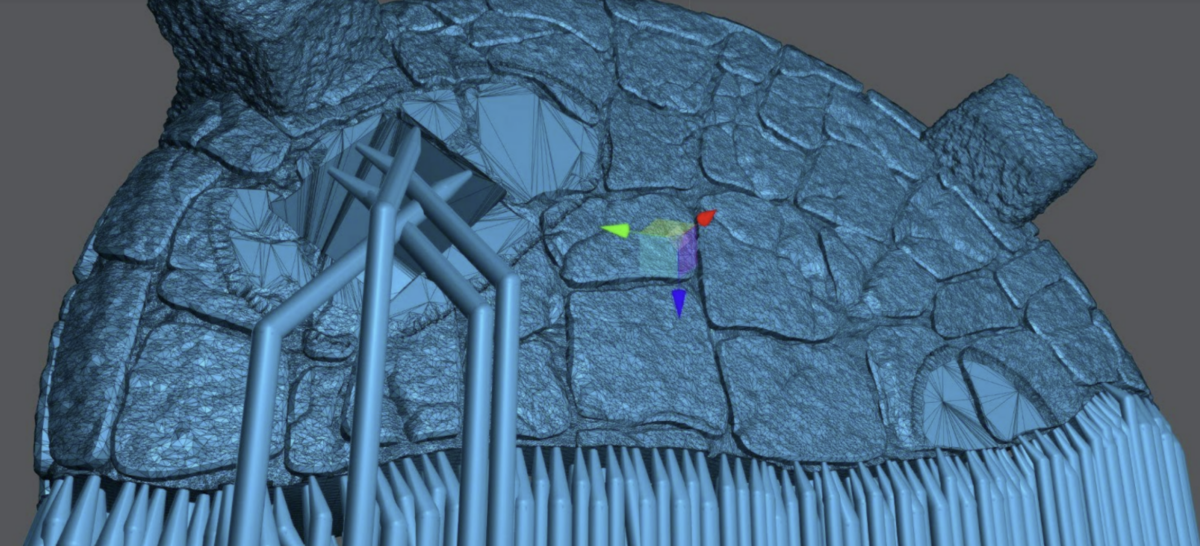
Surface Structure
If you’re trying to preserve the shape of an edge or surface. Place the supports right up to, but not over the edge.
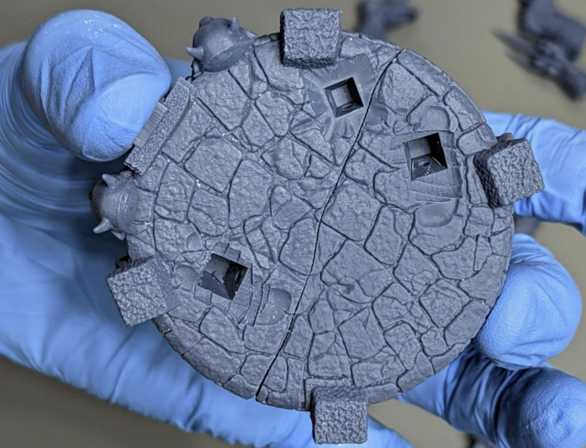
In this example of the base for the TMNT statue I have a complex surface that will be joined to another just as complex. I added a large amount of medium supports with light supports on smaller details like little outcrops in the rocks.
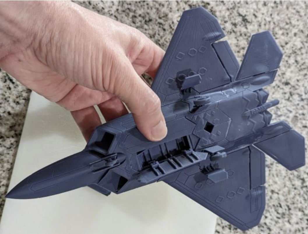
Result before any sanding. I’m holding it with 2 fingers to show I’m not applying pressure to the model, see how there is no stress on the glove.
Mulan Pants Example
The Skyscraper method at work, with the belt and legs.
Only Medium supports are visible, these are anchoring the model to the plate.
Only the Light supports are visible in this, these are ONLY to preserve small details and islands.
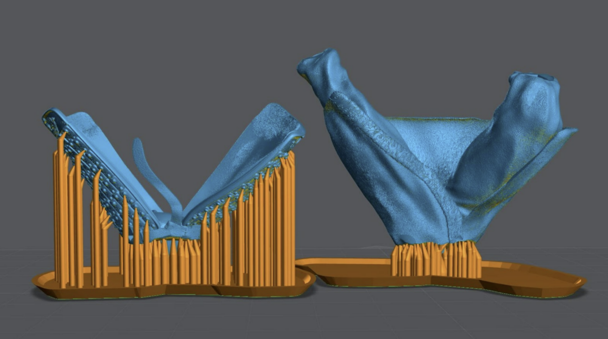
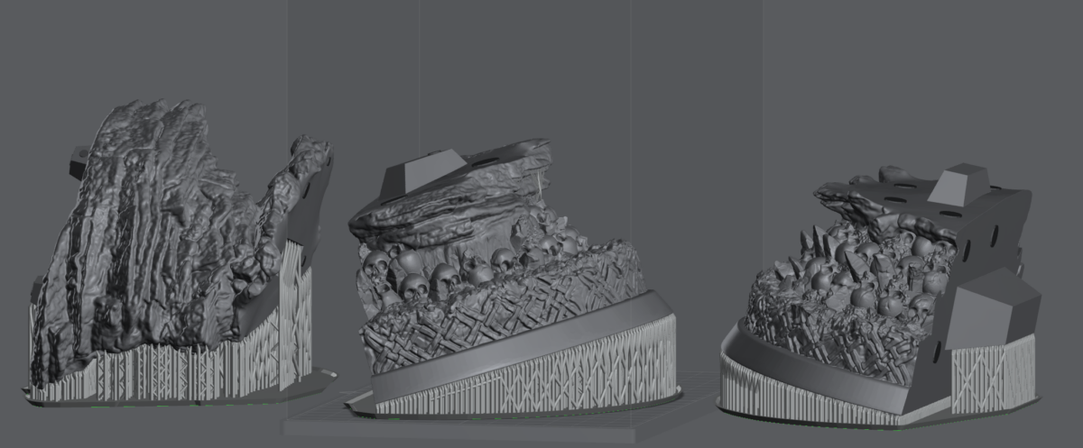
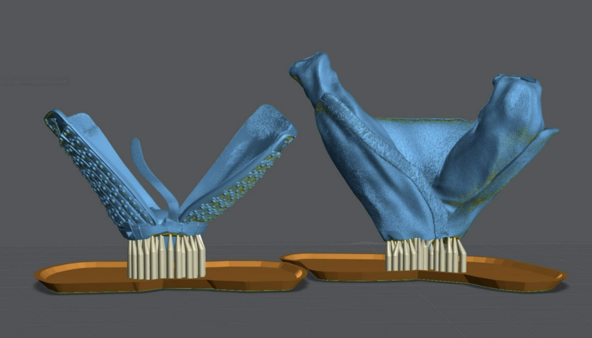
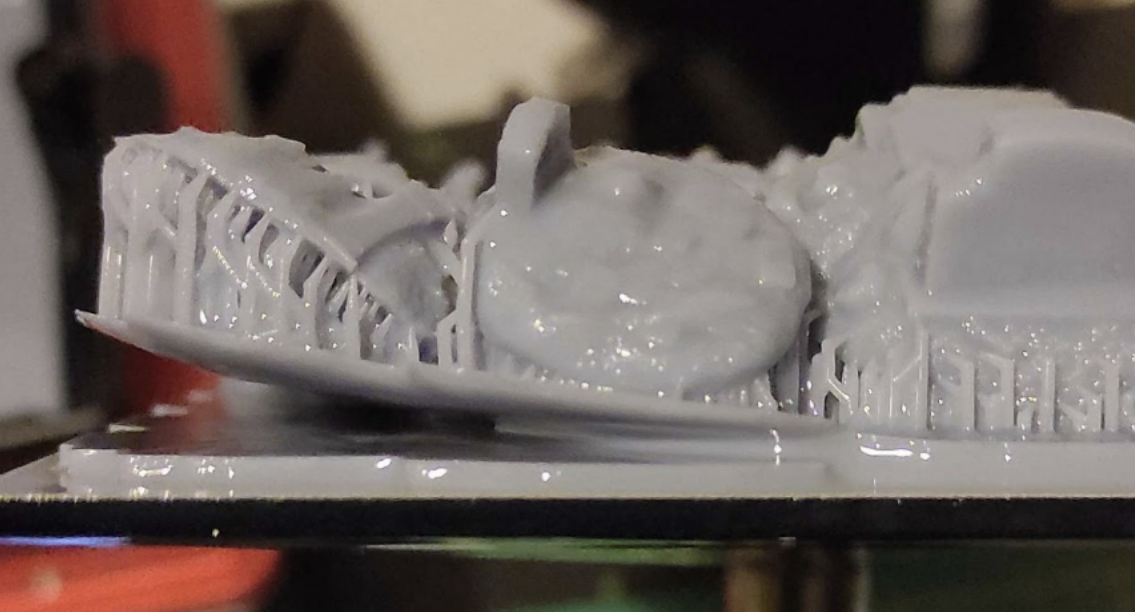
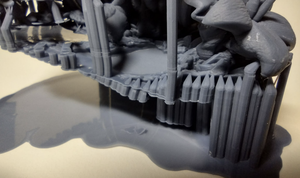
Supporting Large Models
With large models you can get away with:
- Nothing, these suck.
- Hollow always, unless you have a technical reason not to.
- For models with a massive cross section increase your light off delay by 1-2 seconds.
- Hollowing may remove the need to add additional light off delay.
- Hollowing may remove the need to add additional light off delay.
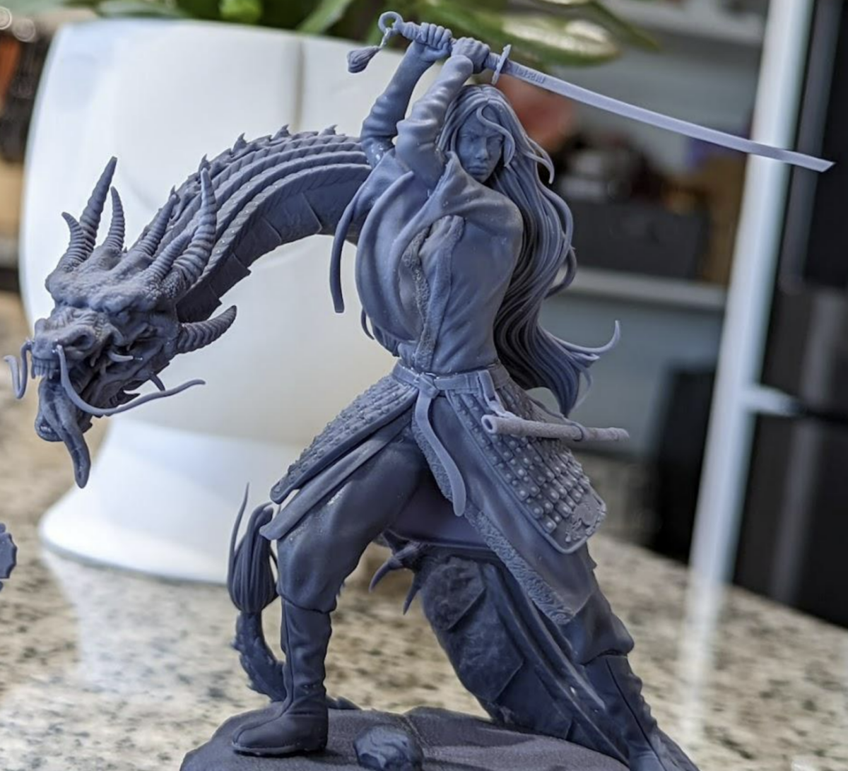
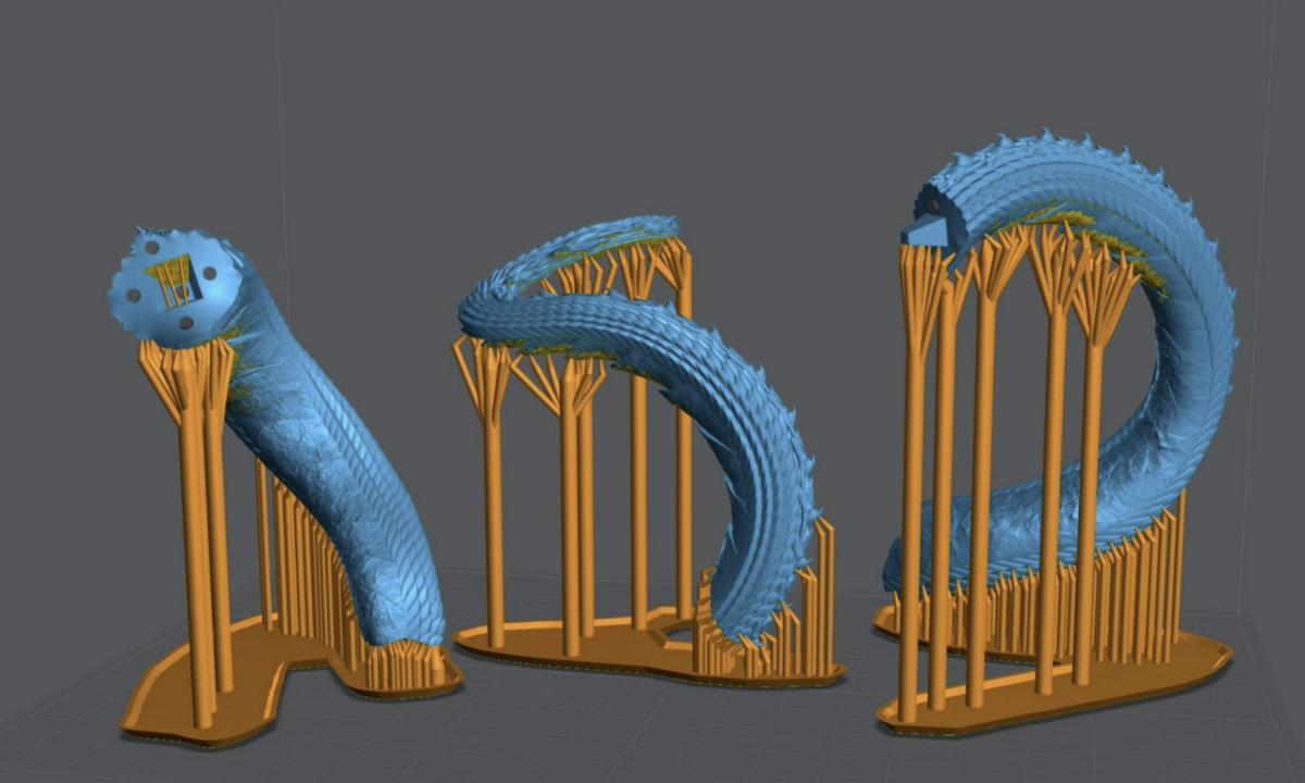
Mulan Dragon Example
Only Heavy Supports are shown. Used to anchor the model and used at “Tree Trunks” for medium supports.
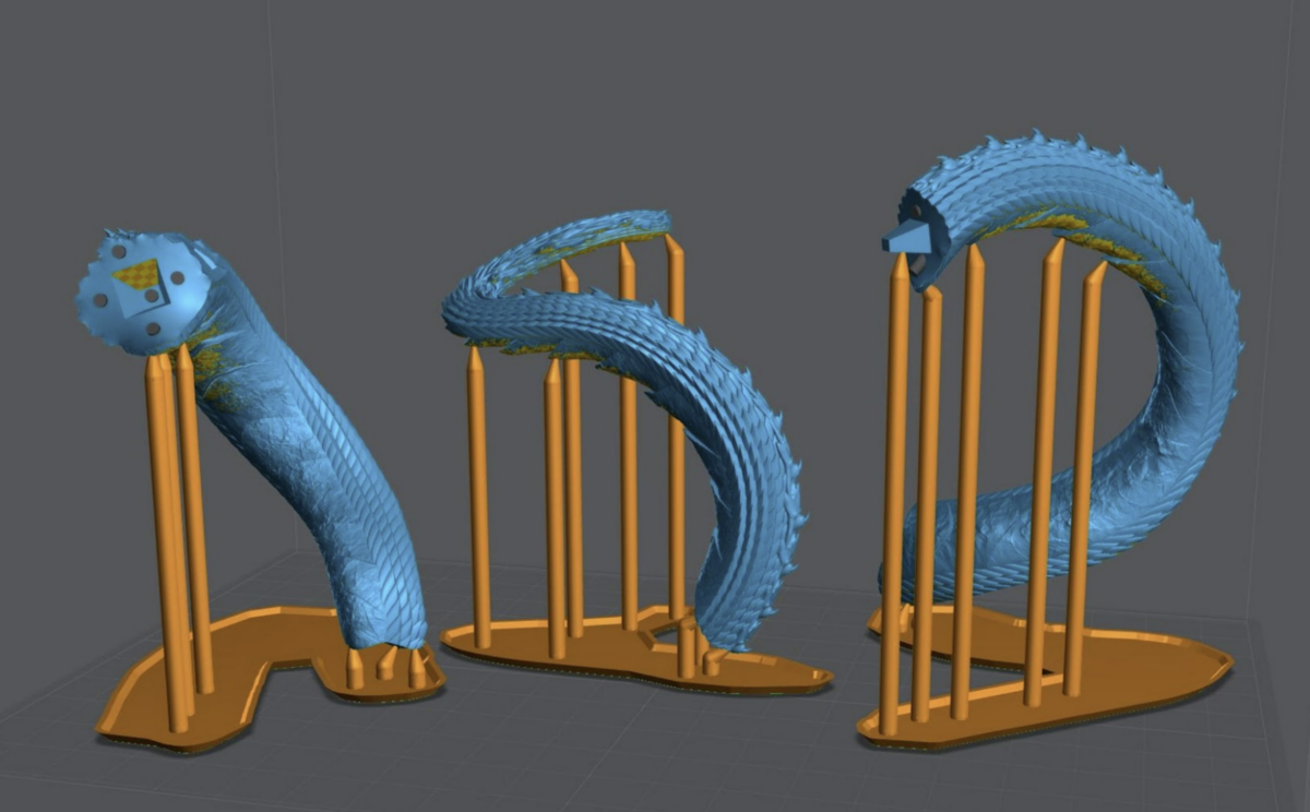
Only Medium supports are shown. They are also used as the tree branches at the top of the model.
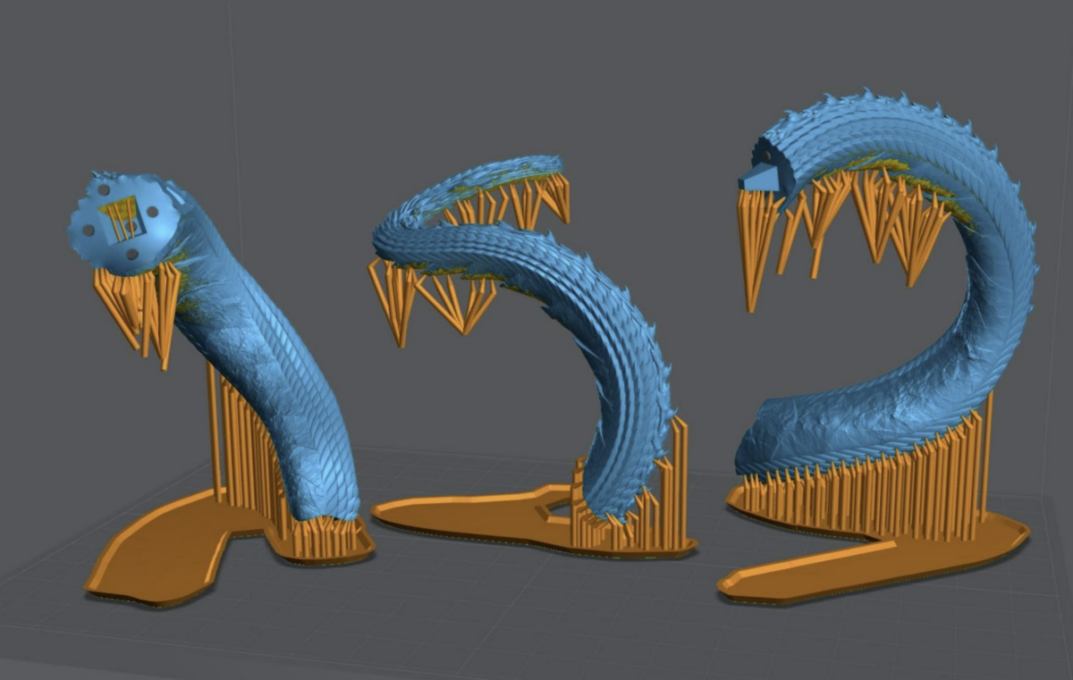
All supports shown. You can see the Trunk and Branches. This is used to cut back on resin used. I typically only do this for taller models where it will make a noticeable cost difference.
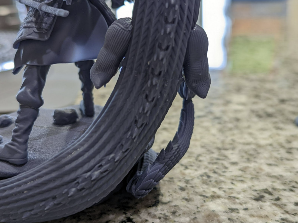
Taken at 4x zoom, from the naked eye the seam is very hard to see. After primer and paint it completely disappeared.
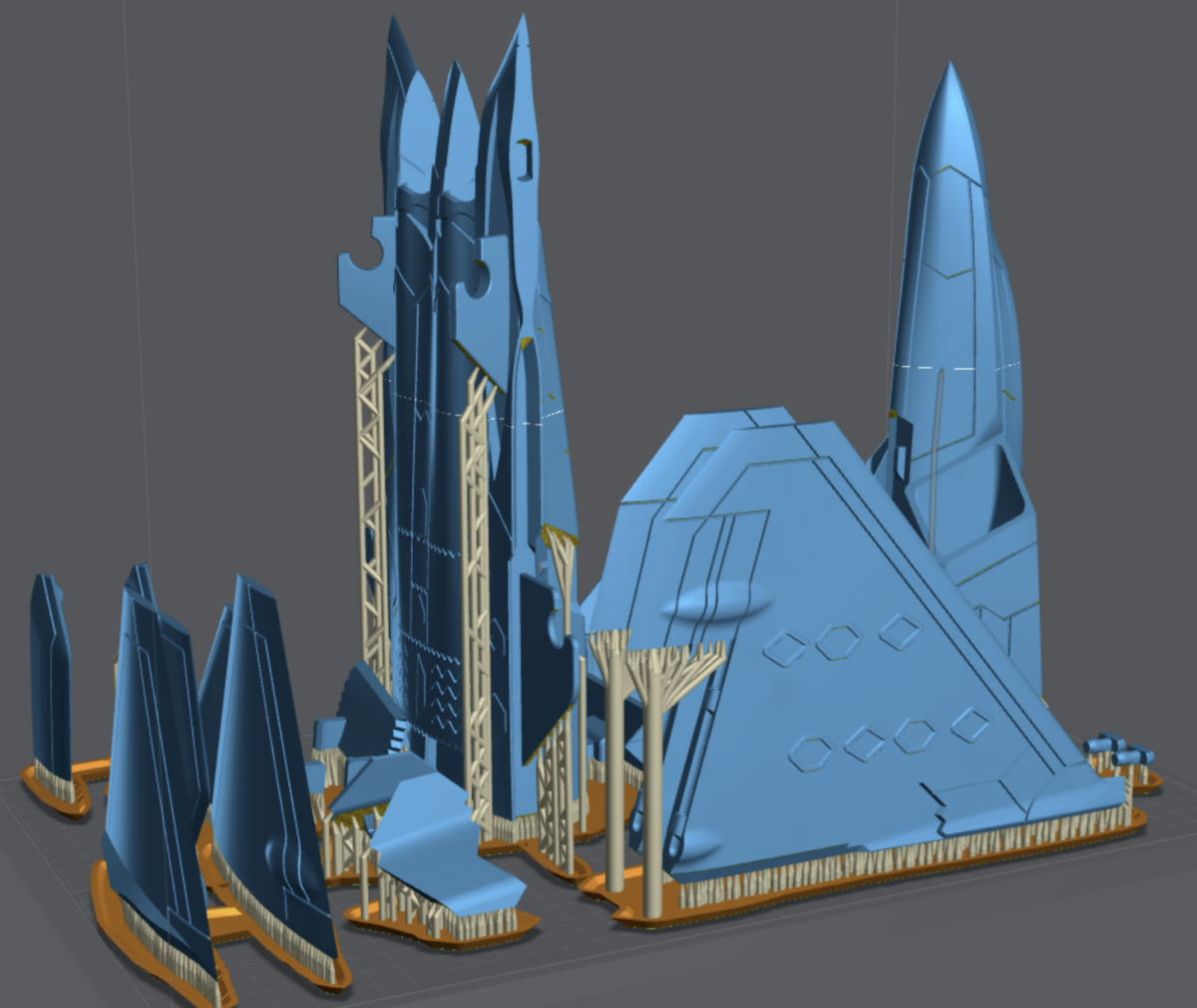
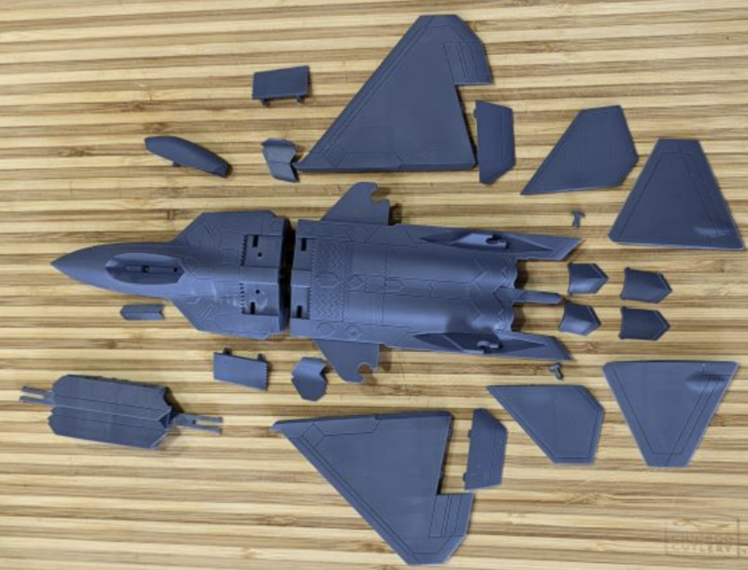
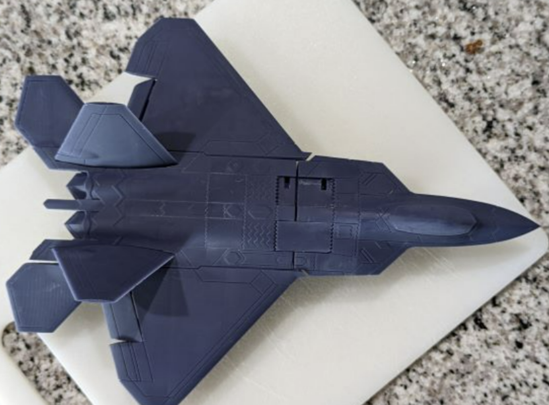
F22 Example
This is a large and tall hard surface object that I could not print on the build plate.
Hollowing
For this section I created a video here. I highly recommend watching it.
If you can hollow, you should hollow. Just don’t forget to add drain holes in locations you won’t see in the finished model.
Pros:
- Saves you money, the larger the model the more you save.
- Reduces suction, better quality prints and less failures.
- Reduces cross sections, better quality prints and less failures.
- Reduces the weight of the model, removing stress on your supports.
- Depending on your model can increase its stability on the shelf.
Cons:
- Not placing drain holes at the lowest sections will lead to suction cups. Suction cups will likely cause print failures.
- Badly placed drain holes can make post processing difficult.
- Time to allow the model to correctly drain before removal of the build plate. (If you care to save money)
- If you don’t clean properly resin can and will push itself out of the drain holes during the curing process damaging your cure surface and the model.
- Depending on your model can reduce its stability on the shelf.
- If you forget to add drain holes, the gasses will cause your model to explode. Sometimes with enough force to throw uncured resin 20+ feet.
- Internal supports may be required.
Hollowing Settings
Thickness
How thick the wall is
In this example the bust on the left is at 2mm, the busts on the right are at 1.8mm
Quality
How many polygons are going to make up the inner walls of your model. The more polygons the higher the quality but this comes at a cost.
In this example the back of the bust is at a quality of 1(min).The front bust is at 4(max)
I’ve personally found 1.8mm thickness and 2.0 quality to be the best for most prints.
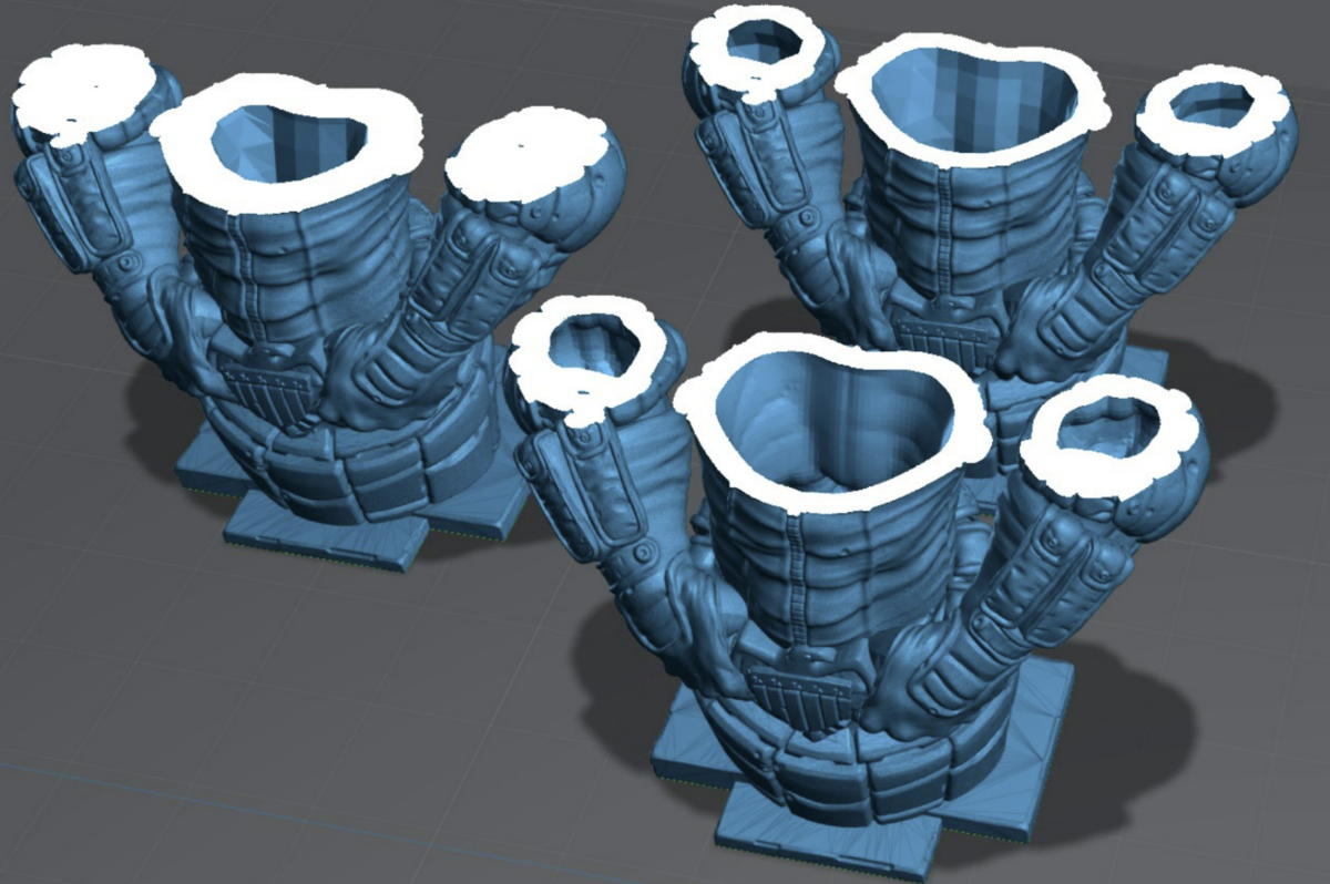
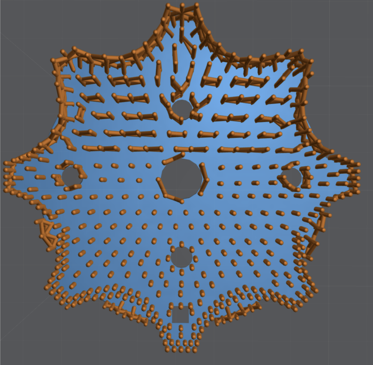
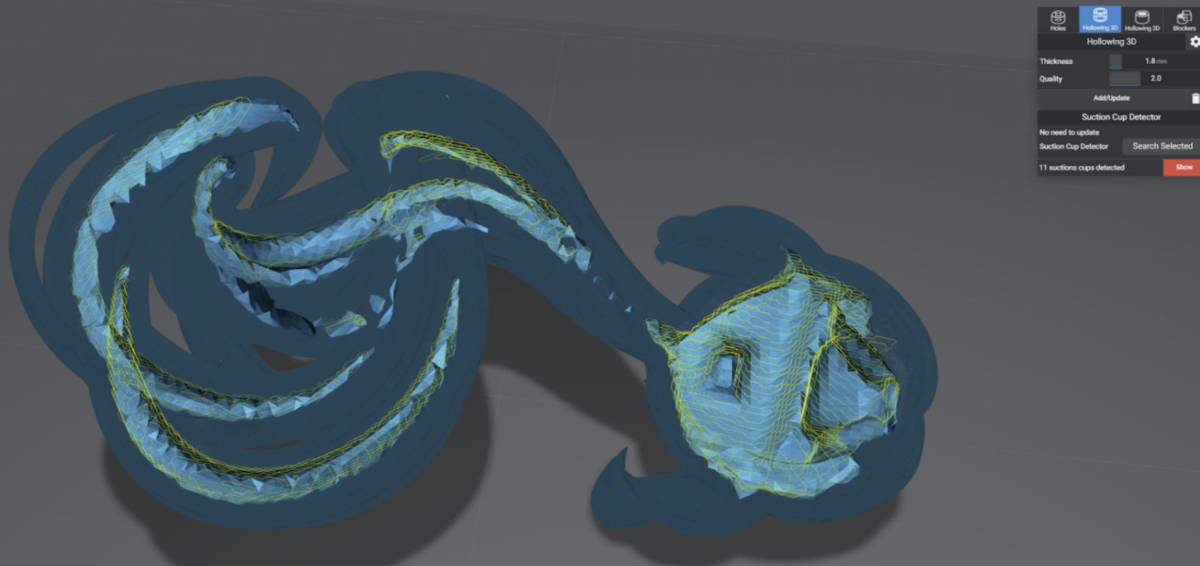
Suction Cups
Not to be confused with peel force or cross sections. Suction Cups are created when you have a void.
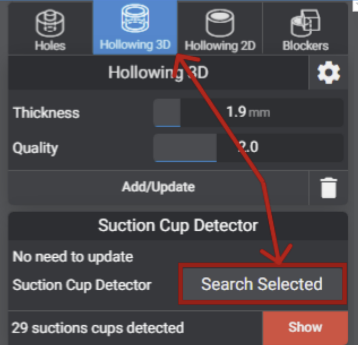
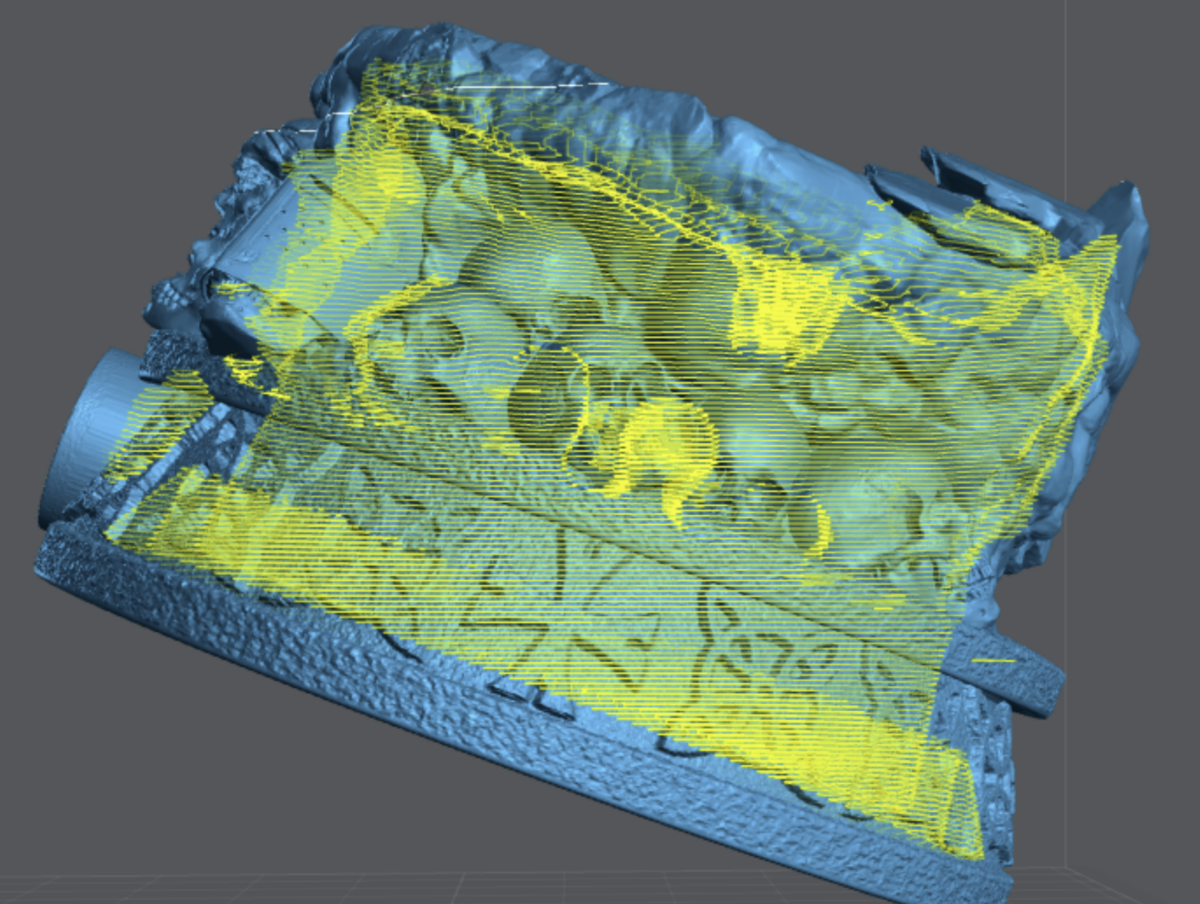
In this Example I used Lychee Suction Cup Detector. Available in the Pro version to highlight the in this print in yellow.
If you don’t have Lychee Pro you can use 3D Builder – Microsoft Apps.
Remember that every void is a suction cup and will need to be addressed if they are too large.
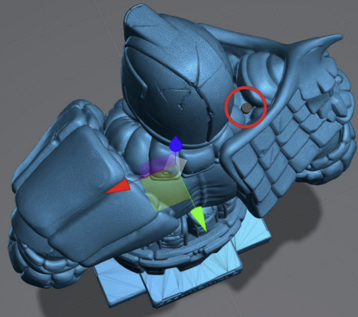
To prevent suction cups you need to place a drain hole in the lowest part possible. Adding more as your print goes on to encourage good resin flow.
In these examples you can see I placed several drain holes. (The black and red cylinders).
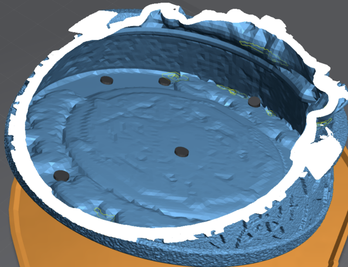
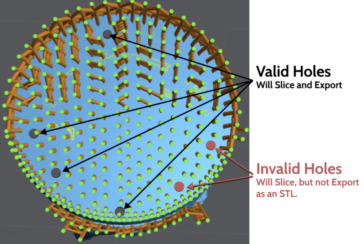
Some holes will be RED this sometimes means that it’s against too much geometry and Lychee can’t Export it. If you try and save this file as a .stl the two red holes won’t be added.
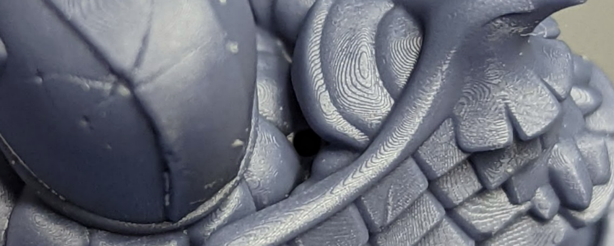
On the top of many models will have Natural Suction Cups. Not all of these can be resolved. However if you’re hollowing a simple hole into the main chamber should work.
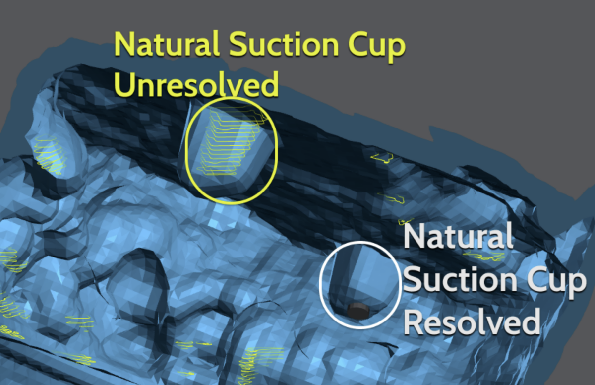
Smaller suction cups, the ones you see in Yellow are ok. They won’t affect the print enough to cause any damage or lower success.
Blockers
Where a drain hole can’t be used, a blocker might be an option. Blockers only Block (prevent) hollowing. This means if the suction cup is created due to the shape of the model a hole must be used.
Blockers can also be very useful in removing resin traps. This is where you have a part of the model that’s large enough to be hollowed, but is surrounded by areas that are not.
In this example you can see all the holes that are not connected. A total of 11 different zones are created when hollowing this hair.
A few well placed Blockers, the 2 Blue boxes, and holes the Red and Black cylinders removed almost all the suction cups. The suction cup in the back could not be resolved with a blocker because it’s a void in the geometry. Only a hole can resolve this. However it’s too small to cause any issues.
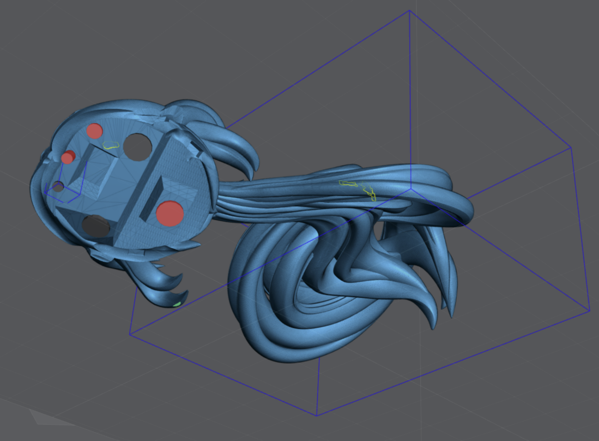
When holes are RED this means that Lychee can’t export them as an .stl, however if sliced from the .lys it will function correctly.
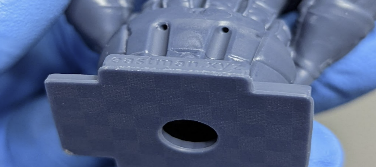
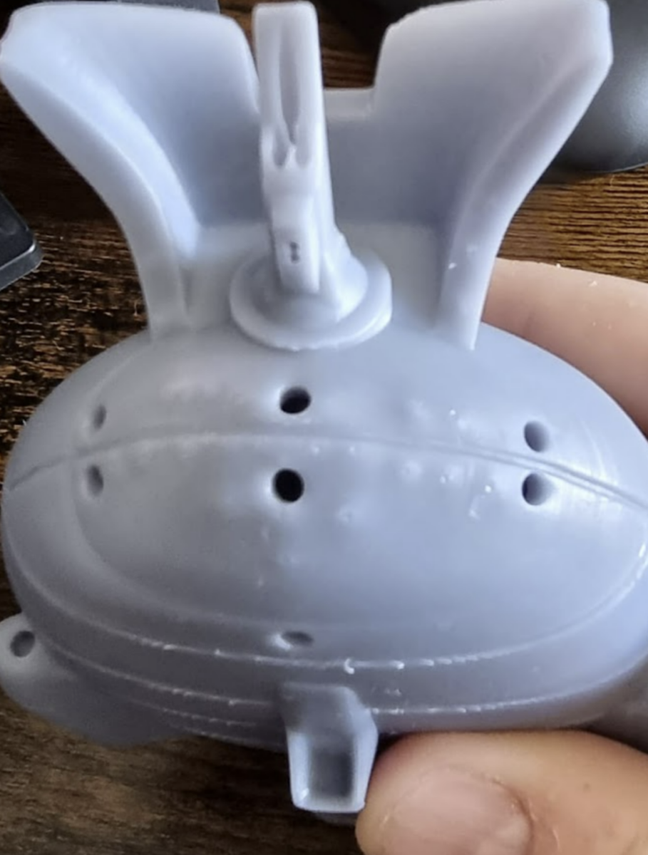
Drain Holes
Needed to allow the resin to escape from the hollows parts of your model. I typically use as many as I can and I try to keep them over 2mm, but the model will dictate.
Always place them in an area that can’t be noticed, or is difficult to notice. Always try and place 2 or more. At least one near the top of the model to allow draining during printing.
Drain holes need to be deep enough and/or angled to penetrate the wall of the model, but don’t come out the other side.
Hollowing on the plate
Some models are best built right onto the build plate but you still want to hollow them. This is difficult because the bottom hold won’t drain till after it’s been removed from the build plate. The trick is getting a minimum of 2 holes as close to the top of the print without causing any damage.
In this example I’ve snuck 5 drain holes into a single print model. Models that are done in one print are more difficult because you have no seams to hide the holes. This is where I find places that will be covered in shadows.
Here is the end result. Pictures taken under bright light and 4x magnification.
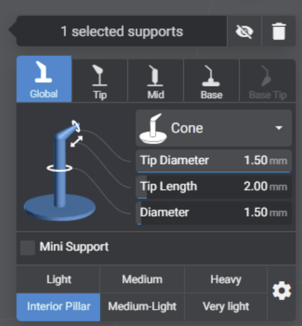
Internal supports
For larger objects you will need to add Internal supports.
WIth Lychee 5.0 you can now have up to 6 support profiles. I highly suggest making one of them an Interior Pillar.
IF you’re using another slicer or the Free version of Lychee modify my heavy support to have a 1.5mm shaft and 1.5mm tip. This way the entire support is now a pillar.
Next change the view so that you’re looking up under the model. There is a toggle on the layer slider.
Now you will support the inside of the model much but with far less support but much larger.
The objective here is to add some support on any large islands but not to small islands.
Finally support the “ceiling”, think of Dwarven or Roman architecture.
Make sure no supports end up going through a hollowing hole!
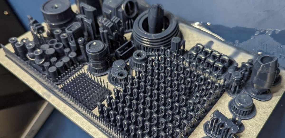
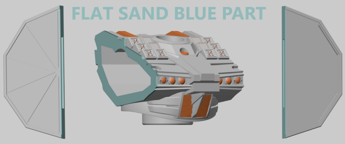
Printing on the Plate
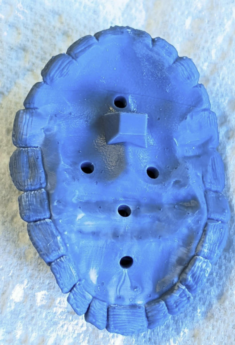
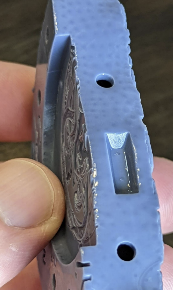
Very helpful if you have an object that needs to be perfectly flat on the surface that is against the plate.
In this example I have 4 parts that will have a flat surface in the final product. Three parts to make up the base and the main chest that will have 2 side caps. All parts NEED to fit perfectly flat for the best result in the final product. Link to Robot model.
Pros:
- No supports needed.
- low chance of failure.
- Perfectly flat surface.
- Great for printing smaller machine parts.
- Great for molds.
Cons:
- Elephant’s foot.
- Some slicers like Lychee Pro have features to help reduce/remove this.
- Can be hard to remove from the plate.
- May still need to be flat sanded.
- Hollowing can be difficult. This is because drain holes can’t be placed on the bottom layers.
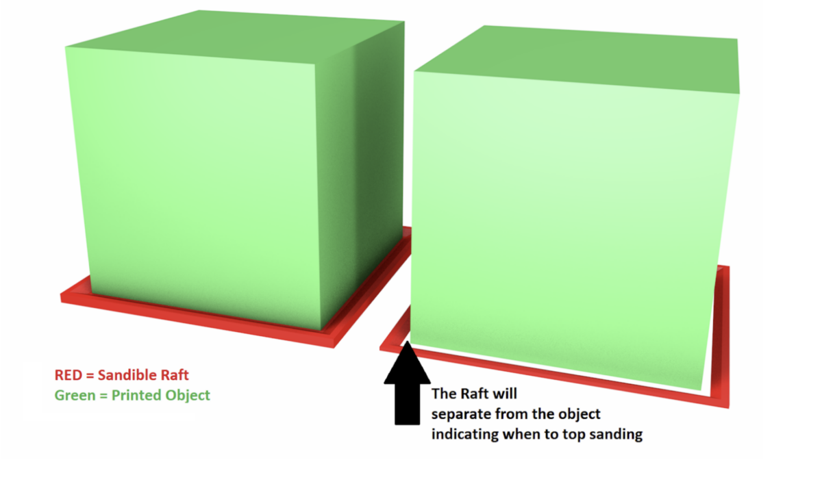
Build in Raft
If you can edit the 3D file, you can also add a raft with raised edges that move away from the print.
This Raft will absorb the Burn-In layers and make it easier to remove.
The raised edges will act as a sanding guide to make sure you sand the print evenly and that you don’t over sand.
Post Processing
Build Plate Removal
You can see my entire process in a video here.
Hold the build plate 90 degrees off of your surface to reduce the chances to throw off your level.
Use the scraper to get under the raft. The model should pop right off.
The Shape Wall rafts allows for easy removal. While also offering a large surface area to hold onto the build plate.
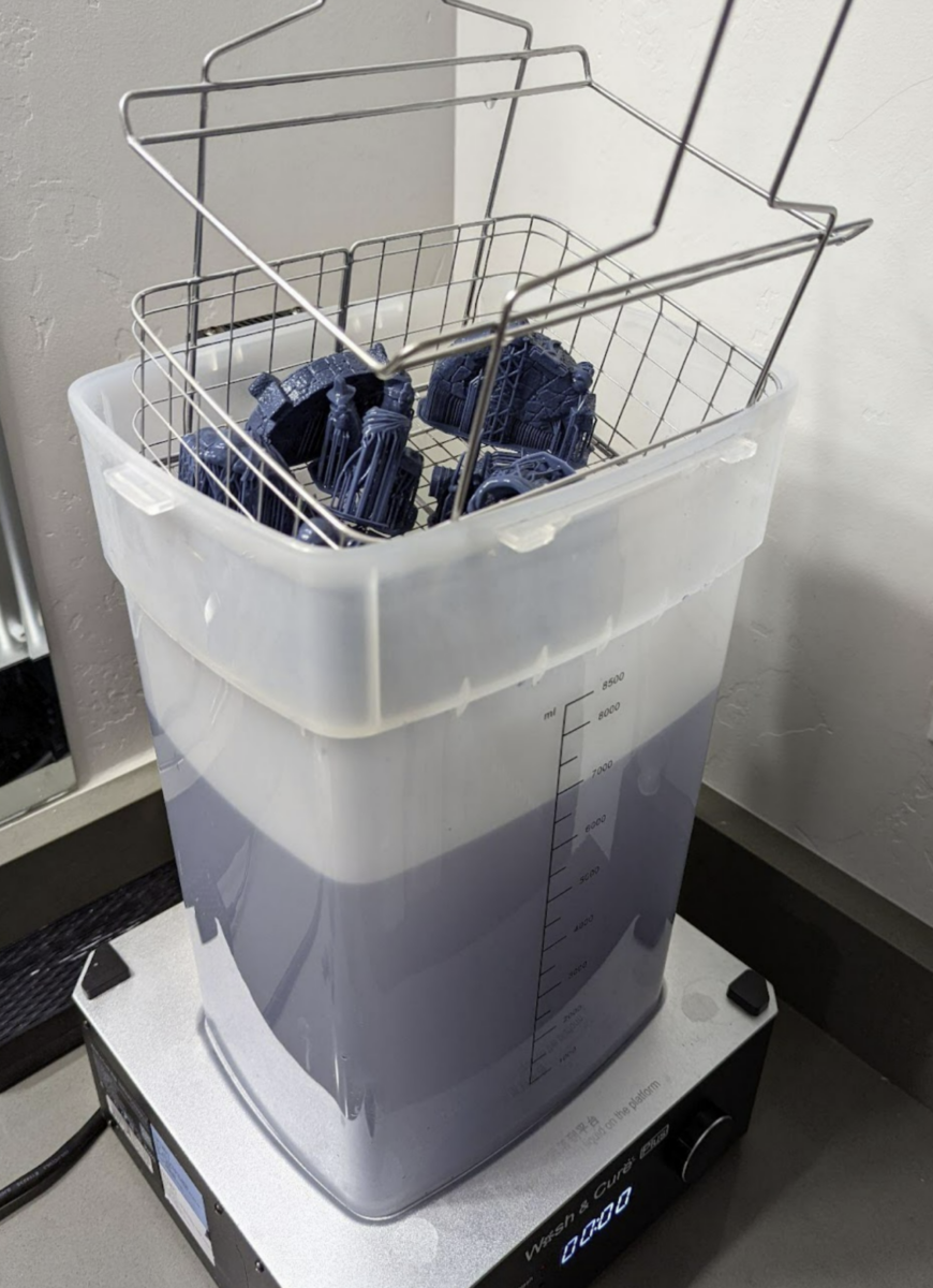
First Clean
I start with spraying IPA over my models right after I remove them from the plate to remove large collections of resin.
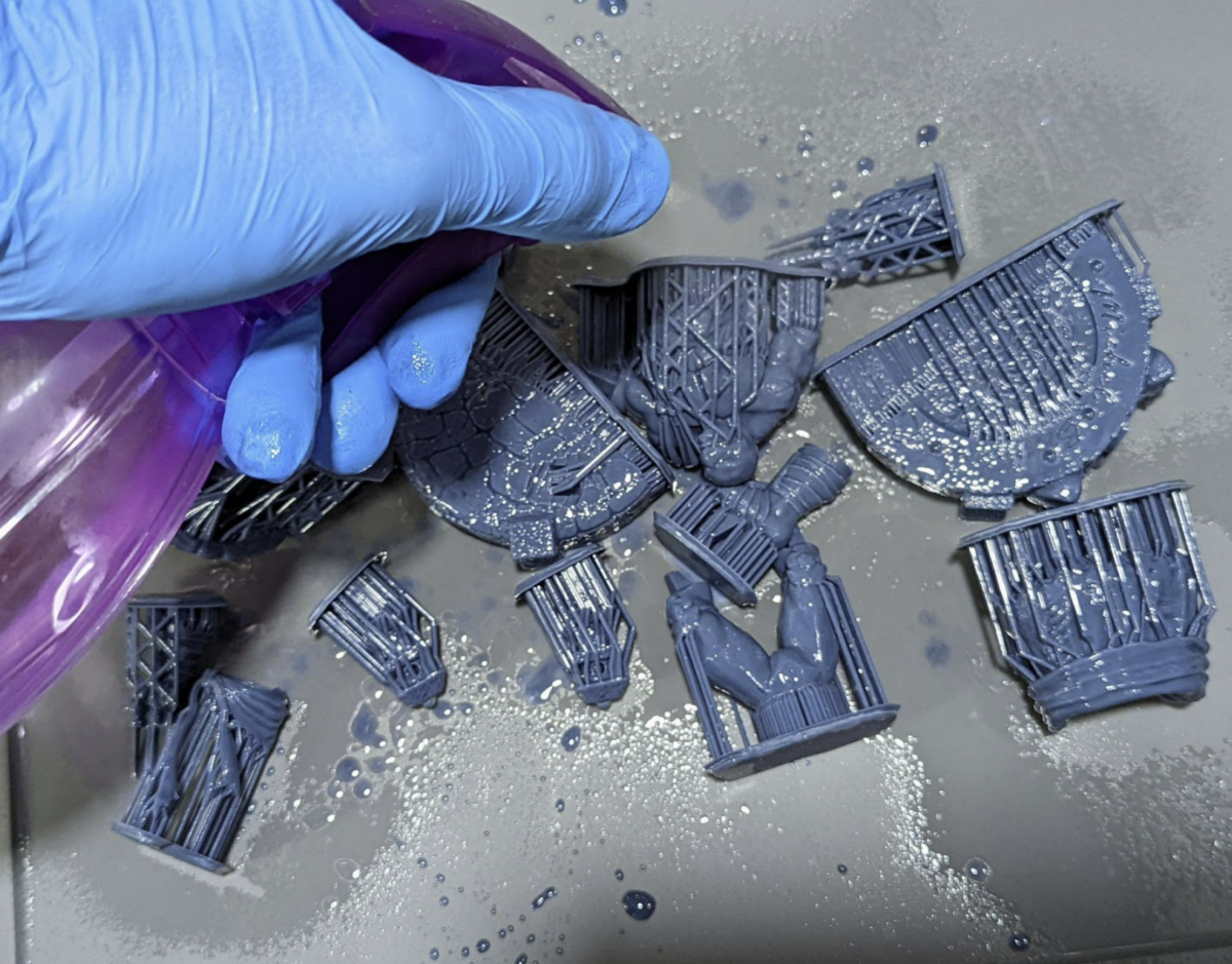
2nd Clean
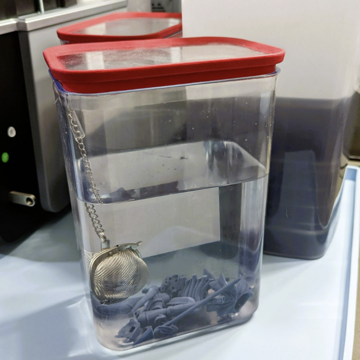
dunk into a very dirty IPA, followed by another quick spray. Then I’ll lightly shake and knock off any extra fluid.
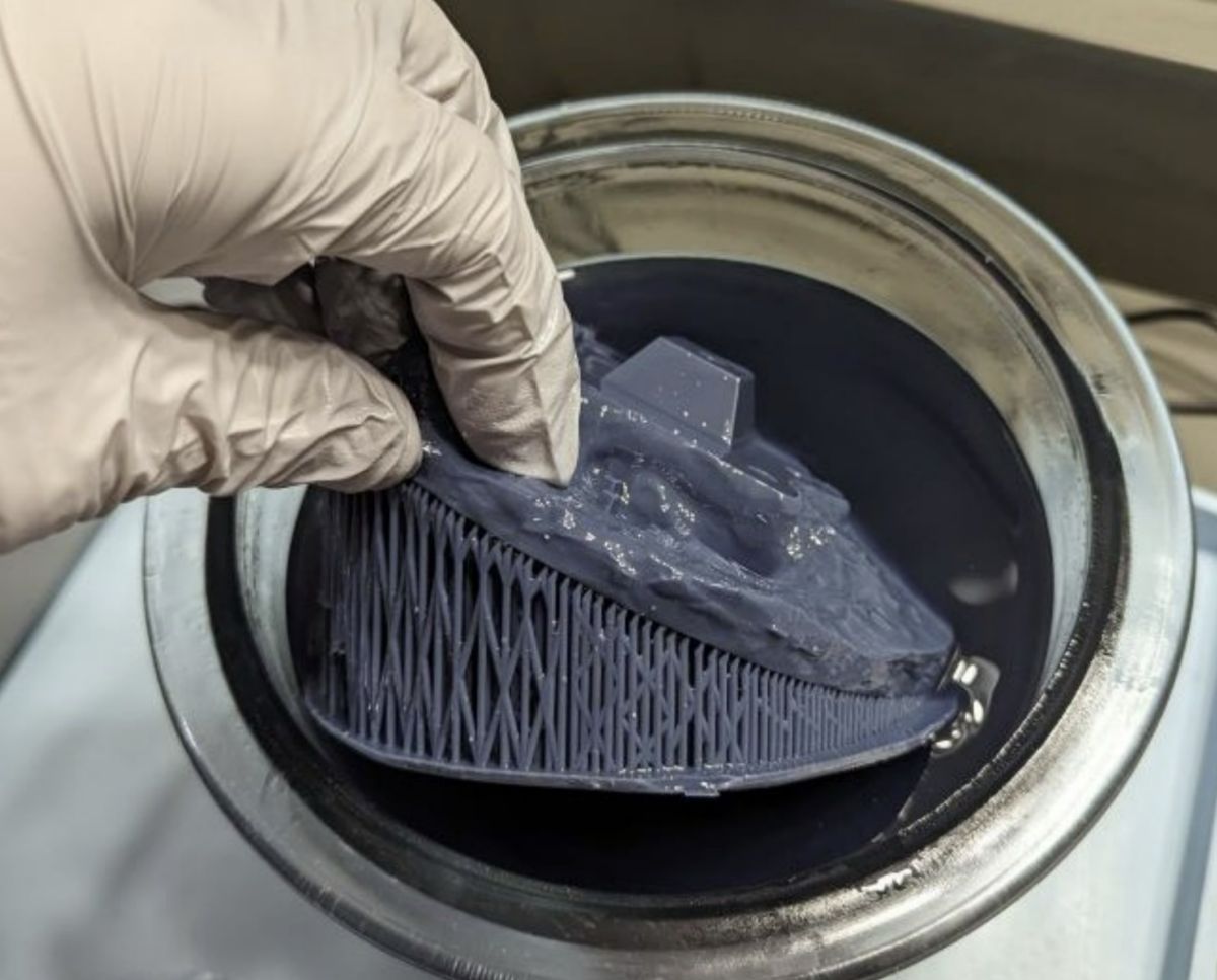
3rd Clean
Main IPA tank where they will sit for 5-10 minutes. I no longer turn on the motor as I found it damages the models by banging them around and suturing in old IPA particles.
Instead I let them sit, then at the end I’ll swish them in the upper layers of the tank.
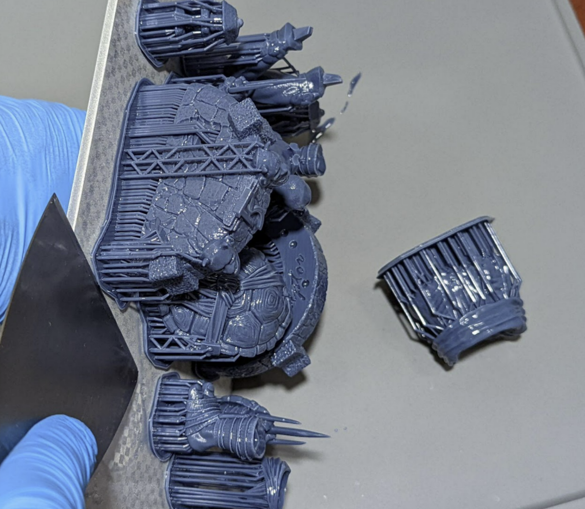
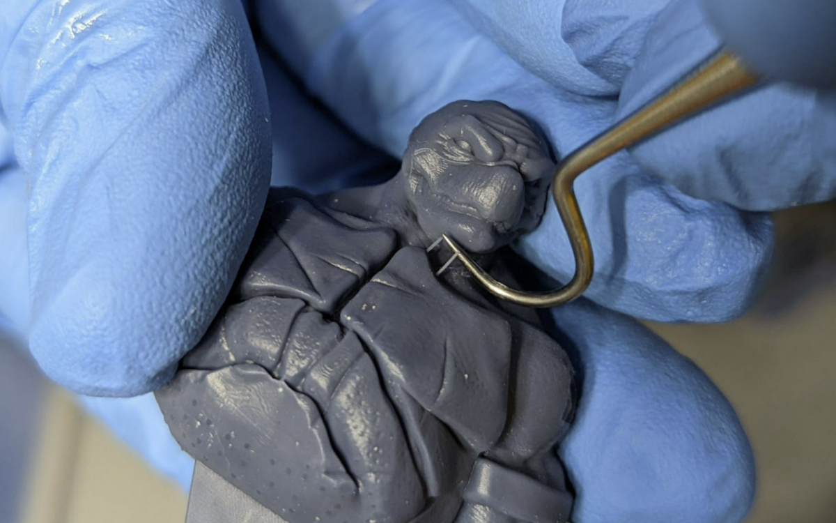
Support Removal
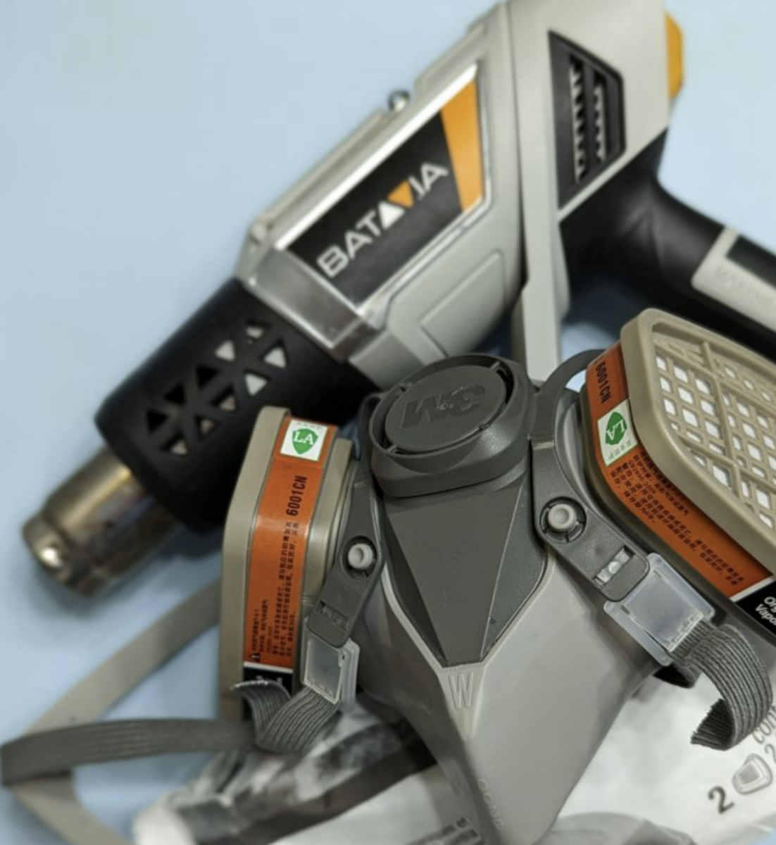
I highly recommend you heat up the supports, then quickly remove the supports while they are hot. If you choose to do this using a heat source, you NEED to wear a mask.
Hot Water Method
Put the print in a bucket of hot water and let it sit for about 30 seconds, then remove the supports. The result is pretty good, however, I don’t use or go into detail on this method as it has some major drawbacks.
- Some resins react with the water, especially if you leave them in there for too long.
- Heating the water adds time and more equipment as you don’t want to mix this process with your kitchen.
- Disposable of the now contaminated water. IT CAN NOT be dumped in the drain. Leave it in the sun and allow it to evaporate before dumping the build-up resin.
- Models wet with water take 6x longer to dry than wet with IPA, even longer if they are hollow.
Three examples of why I recommend this, best to watch these with sound.
https://imgur.com/7hZKJeF
https://imgur.com/MMQYA3j
https://imgur.com/eZZGobd
If the resin smokes you got it too hot. This will not ruin the model as by now you have removed 99% of all extra resin, but it will create toxic smoke.
I use this model because it has a low heat setting. Don’t use the high setting and melt a glove to your hand please.
Warm supports almost just fall off leaving less damage.
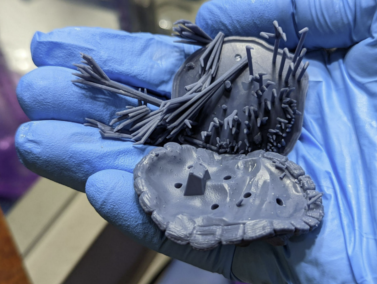
Remove any leftover supports using precision tools, I use this set of dental tools.
4th Clean
After the supports are removed, I run them for a final clean. This is not always necessary but it can make a noticeable impact.
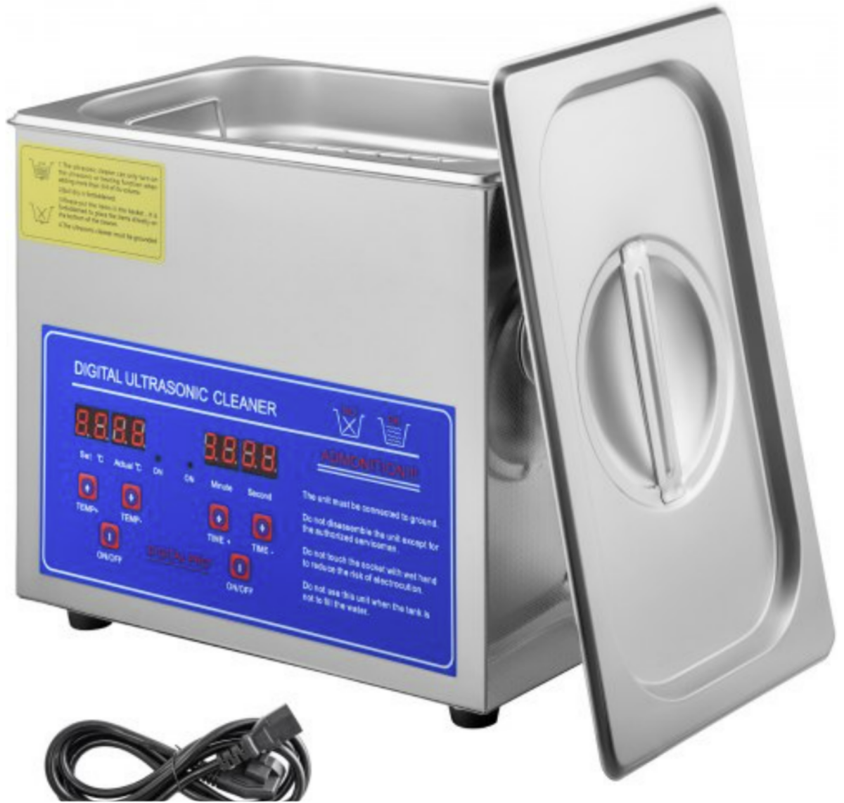
You can use an ultrasonic Cleaner. This model costs $70. DO NOT USE THE HEAT FUNCTION, MUST BE IN A VERY WELL VENTILATED ROOM WHEN IPA OR RISK SERIOUS BODILY HARM!
The safer and cheaper method is to have another bucket with very clean IPA for the final dunk and wash. I’ll let my print sit in this for about 3 min.
Final Dry
Make sure your models are 1000000% dry before you cure. Let them sit for a very long time or use a mechanical tool like a heat gun to dry them off. Wear a mask when using heat guns around resin.
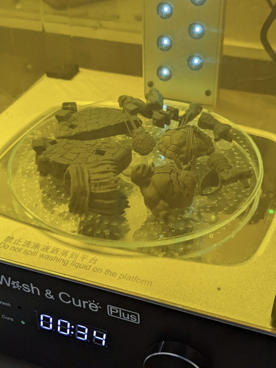
Final Cure
Do a quick 30 seconds then check for any dripping resin. Especially from hollowed models. Flip the models and do 3min, repeat till your resin is fully cured.
Can you Over Cure resin 3D prints?
No, but also yes.
Fast ABS like “hard” resins, the UV reaction will continue till there are no more binders to react to the UV light. At this point the resin is fully cured & more UV will have no effect.
Flexible, clear or Cast resins, you CAN over cure them. But in post curing, and when printing. Be careful using a calibration part that could lead to overcuring. These need to be cured in a way that preserves the color, flexibility or burn out. It’s best to follow the manufactures post cure processes.
Wear a mask and UV glasses when using a UV light. When using a cure station, leave the room. This will create toxic fumes.
If you don’t have a cure station I recommend the Beast UV Flashlight. Remember always wear UV glasses, or you can go blind, your choice.
Cleanup and Disposal
Trash
Make sure you cure all your supports, used paper, used gloves and any resin waste.
I throw them into the trash and use my UV flashlight to cure them all at the end of each print. You may also choose to throw everything into a small clear container and cure it using a flashlight or your cure station before you dispose.
Cleaning your FEP
See my video on how to properly clean you FEP here
Do this after every print unless you use the silicone spatula method to stir and check your FEP before every print. Most 3D printers have a tank clean option, see your manual on where to find this function.
Keep a stash of tall supports that you can use as handles to easily remove the cured resin from the tank clean process.
- Place one of the saved supports near the edge or corner. Lightly press the Raft of the support against your FEP.
- Run your Tank Clean Option normally for 10 seconds. In some printers it’s called exposure.
- Pull on the support towards the center of the VAT. This should peel the cured resin off of the FEP along with any trash from previous prints.
- Move the cured sheet of resin away from your printer and cure it the rest of the way before disposable.
Emptying and Removing The Vat
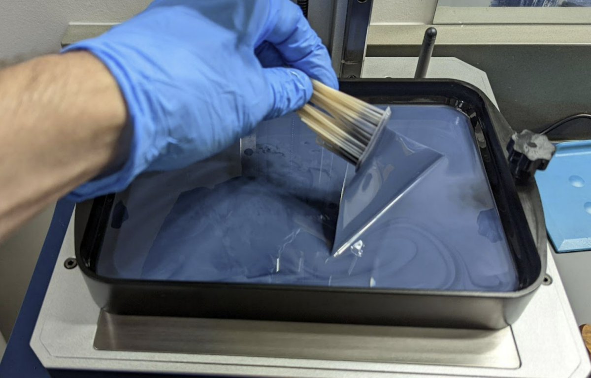
I highly recommend buying a large syringe to suck the resin out and run it through a paint filter back into your resin bottle. Find the link at the bottom.
Once your VAT is mostly empty it’s much easier to pour the remainder into the filter by hand.
Every time you remove your VAT you expose your LCD to dust, hair, falling objects like build plates and resin. This is just one of the reasons to level in the VAT.
- First remove your build plate, you DON’T want it to drip resin down on your exposed screen.
- Remove the VAT
- Remove the resin using IPA, even water washable.
- Dry it using clean paper towels.
- Buff streaks out using a lint free cloth.
- Blue painters tape to remove any dust and hair.
- Proceed to Step 8.
Clean your LCD
- Clean it using IPA.
- Dry it using clean paper towels .
- Buff streaks out using a lint free cloth.
- Blue painters tape to remove any dust and hair.
- Reinstall the VAT as soon as you can to protect your LCD from getting damaged/dirty.
- Make sure the VAT is secured down fully.
- There is no need to re-level your 3D printer after this.
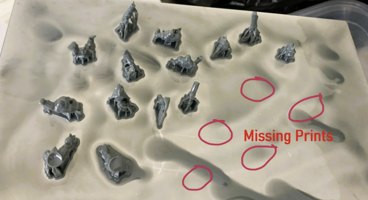
Troubleshooting Print Failures
Layer Lines
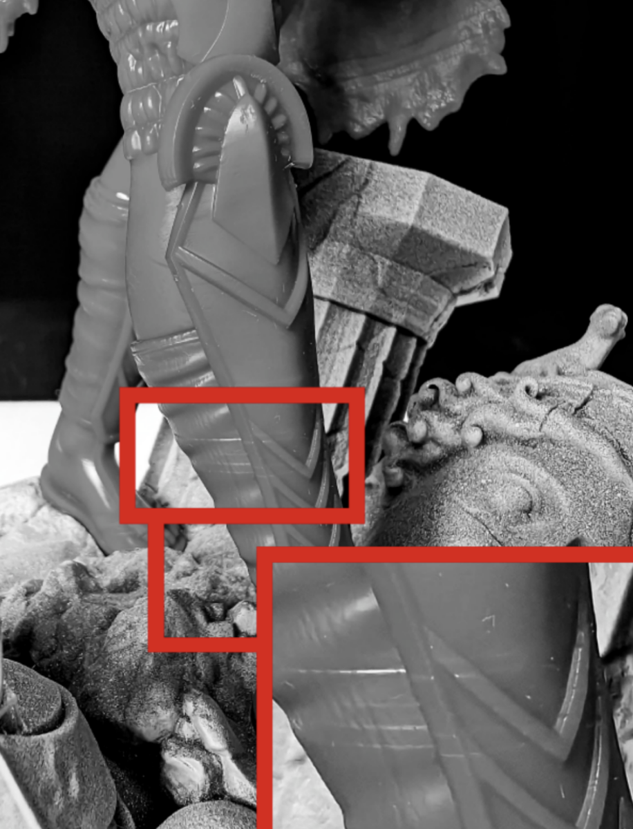
Layer lines can be very frustrating, potentially ruining a perfect print when in the wrong place. Here is a list of potential causes.
- Not enough supports to keep the object solid on all three axis.
- To fast lift speed
- Low temps
- Hollowing with no suction release.
- No rest time (Light off Delay)
- Temperature changes during the print
- Pausing the print
- Adding resin during a print.
- Power delivery issues during the print.
- A dirty printer causing the rails or screw to catch.
Volcanoes
If you ever see these large bumps on your 3D print it could mean a few things.
- Not enough supports and/or your support tips are oversized.
- The weight of your model is creating too much surface tension.
- Massive peel force, caused by large cross-sections.
As volcanoes can be caused by multiple things there can be different ways to resolve it
- Add a LOT more supports with ~0.4mm tips
- Reduce the weight by using hollowing
- Reduce the cross-section by hollowing or different orientations on the plate. But not forgetting the skyscraper method.
- If you have the skill, slice the model into smaller parts. This resolves issues 1-2. You can even place the supports in sections that will be internal, completely hiding support damage in the final product.
Just the supports
When your build plate looks like this it means really one thing and one thing only.
Not enough support, but why would I say this is most likely the cause?
What do we know?
- The rafts are not lifted in any of the corners but are secure to the build plate, this means;
- Burn in layers are correct.
- The build plate is level.
- The supports are fully formed down to the tips, this means;
- It’s not an issue with under exposure. Please STOP adding UV exposure time to resolve an under supported model.
- The USB drive is in good condition.
- The models do not have bad geometry. This would cause some parts to fail and others to print.
- The pulling force (Bed raise speed) is probably not an issue.
- The supports are different showing multiple models of different heights and size, this means;
- It’s not an issue with room temperature changing, as this would cause failures at different places on different models.
- It’s not a suction issued caused by a larger model
- It’s not a weight issue caused by a large cross section.
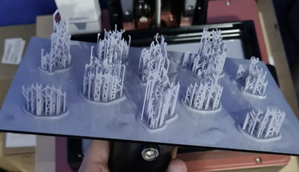
After eliminating a lot of things, what’s left? Well, not enough support.
The fix: Increase support contact with the model.
- Add 4x times the supports, and yes I do mean 4x at minimum.
- Make sure you’re using the correct support sizes.
- Medium support tip of 0.40 mm is the correct size to anchor any models of any size if you have enough.
- Light supports, like the ones you see in this example are ONLY used to keep small details.
- Do not attempt to use lightsupports in any quantity to keep a model to the plate.
Split-Rafts Or Partial Supports
- The quantity of burn in layers including transition layers are too many. Causing them to bleed into the support shafts. Or your raft is too thin. You want a 1.0mm raft min.
- This can also cause an issue of hard cured resin next to soft cured resin causing raft separation.
- Your burn-in layer UV exposure is fine but your supports shafts are undersized.
- Your lift speed is too fast.
- You have bad resin. Bad resin could mean, not mixed well, a bad batch or ECO resin.
- Energy supply inconsistent
- This kind of error could also be caused by an inconsistent energy supply from your network. Try moving your machine to another outlet which you know is not within the same electrical line.
Nothing on the Build Plate
- Make sure that your resin is mixed well, including squeegee the FEP to pull in the layer that separates from the resin.
- Print above 20c, preferred 25-30c.
- Be sure your Build Plate is properly leveled.
- A FEP free from excessive damage.
- 5. A clean LCD free from any fibers or streaks.
- 6. 4-6 burn in layers, 3-6 transition layers.
- Increase burn in time by + or – 4.0s till the model sticks but is still easy to remove.
- What works for one size of object, may not work for another. Use the Small, Medium and Large method I talk about in this guide to calibrate for each.
- You need more Light off delay (Waite Before Print).
- Your Retract Speeds are too fast. Try to keep them under 100mm/m. If your printer supports TSMC, slow down to under 60mm/m for the final 1-2mm.
Half of the prints stuck to the Build Plate
Your bed is not level
This can lead to a full failure. More common, are prints in the middle or one side of the build plate are successful. However, prints on, the opposing side are hanging off or failed completely.
Safety:
THESE ARE NOT OPTIONAL!!!
Respirator An N95 mask is not sufficient.
Organic vapor cartridge.
UV + Safety Glasses Keep resin and UV light from taking away the reason you do this in the first place.
Gloves – Wear appropriate chemical-resistant gloves (nitrile or neoprene) . I’ve discovered that gloves under 5mil DO NOT offer enough protection.
My recommended items for 3D printing
My Favorite Resin
Siraya Tech Navy Gray, for better results mix in 15% Tenacious Obsidian Black.
If you’re in the USA I highly recommend buying it by Navy Gray 5KG Jug for the best price.
If you need a very strong resin, hit it with a hammer resin. Or a resin that can have prolonged skin contact use Blu. For best results make sure the resin is above 30c during the entire print, I prefer 34c.
Disclaimer: I do get 5% from the Siraya Tech links in this guide. I recommended them before this, and would recommend them if I no longer did. None of the other links are affiliates, my youtube channel is not monetized.
Greatly Improve Print Quality and Success Rate
Temp Sticker for your VAT. KNow the temperature of your resin, this is very important.
Heater Option 1 – Easy to install, more power usage heats up the entire printer.
Heater Option 2 – Less power usage but longer heat up time. Makes vat cleaning a bit more difficult.
Resin Printer Cleaning
Silicone Mat – Keep your area clean, these animal mats are cheap and large. They work VERY well!
Larger paint strainers – Used for cleaning IPA and Resin. The larger ones help prevent spills.
Soft Silicone Spatula – Large for mixing, very soft and flexible to not damage your FEP. I very highly recommend this!
Syringe – For no hassle and mess of emptying your VAT.
Funnel – You only want the red one, the other ones you can use for whatever else.
Filter – Paint filters are fantastic as you can cure and throw away the mess.
KimTech Wipes – When you NEED to clean the FEP mostly when switching resins. Use these to not scratch the FEP.
Resin Printer Maintenance
LCDTape – If you ever have to replace your LCD, screen protector or it’s just time to replace it.
Super Lube 21010 – Make sure you keep your rails & screw clean and lubed, you don’t need much.
Printed Model Post Processing
Dental Tools – for removing hard to reach supports. I very highly recommend these! The flat one can be used to scrape away resin for better fits. The smallest one to remove hard to reach supports.
Heat Gun – Drying and removing supports, don’t use the hottest setting. I very highly recommend this!
Glass Jars – Wide mouth for Stage 1 and 4 cleaning.
UV Flashlight – Cure all your resin waste. I very highly recommend this!
Trash Can with sealed lid to reduce odor, more expensive but better version.
Consumables
IPA Use 95% – 99%. If you use my Cleaning method this will last a very long time.
Resin– 5KG – This is one I use but there are many resins for different applications.
Super Glue – Complete control with no mess, even on very small parts. If you heat the part a little, it will cure on contact so be careful. Will not break before the resin does.
nFEP – Better than a normal FEP. Make sure it’s large enough for your printer.
Power – If you live in an area with insinconstant power or in an older house, this can be very important.
Battery – Cheaper UPS with USB for filters
Larger Battery – Larger for multiple printers or longer outages
Focus
Coffee Press
Coffee
Manufacture Resin Profiles
I hope you enjoyed this guide. If you have any suggestions, questions or snide remarks, feel free to reach out on our discord channel at http://bit.ly/3ZP9z6Y